Blog
Cable Gland Torque Specifications and Sealing Points Guide
A practical guide to cable gland torque specifications and sealing points, covering nylon, brass, and stainless steel torque values by thread size.
Read More
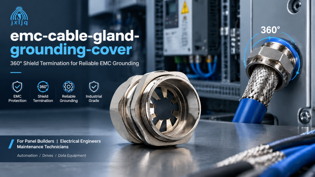
Grounding an EMC cable gland correctly is what turns a shielded cable entry from a potential antenna into a real shield bond. When a shielded cable passes through an enclosure wall, the screen must be connected to the grounded enclosure around its full circumference — a 360° termination — so interference currents are drained at the entry instead of radiating into the panel. This guide explains how EMC gland grounding works, why 360° shield contact matters, and the exact installation steps to achieve a low-resistance bond that survives in service.
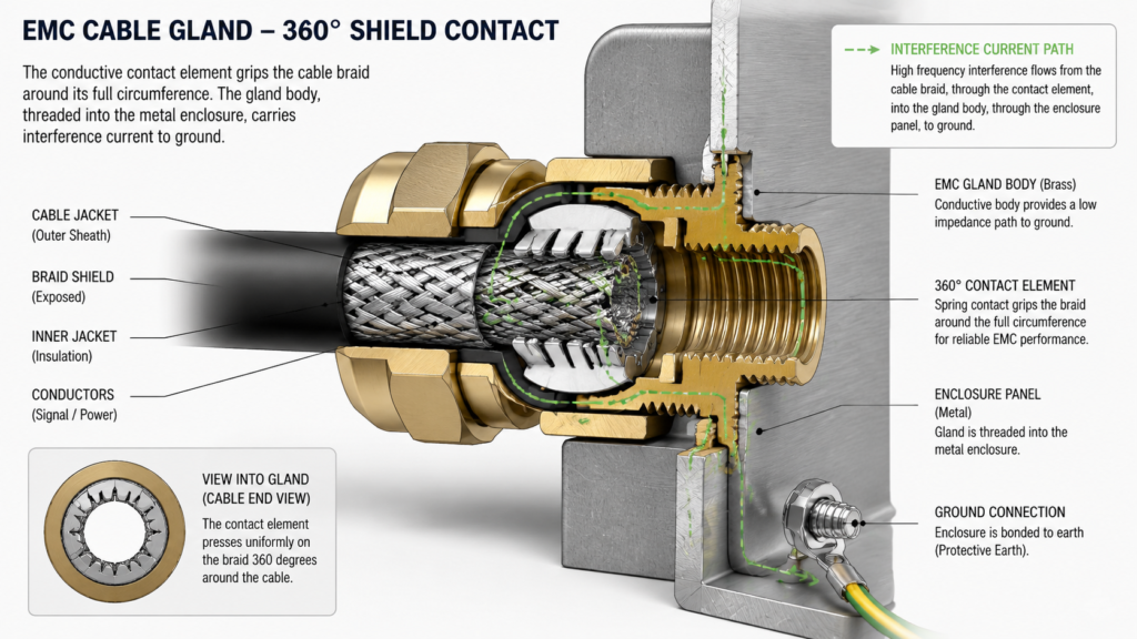
An EMC cable gland grounds the cable screen at the point of entry. Inside the gland, a conductive metal contact grips the exposed braid or foil shield of the cable. Because the gland body is threaded into a metal enclosure, the electrical path continues from the braid, through the contact, into the gland body, and on to the grounded panel or cabinet.
Two things must both be true for this to work:
This is the same principle described in our overview of how an EMC cable gland works — the difference here is the practical job of making the ground connection reliable on site.
The most common shortcut when terminating a shielded cable is to twist the braid into a tail and land it on an earth terminal. This “pigtail” drain wire is fast, but it adds inductance in proportion to its length. At the frequencies where interference is a problem — switching drives, data links and radio noise — that inductance turns the shield bond into a high-impedance path, and part of the noise is radiated or coupled back into the conductors.
A 360° shield termination clamps the braid around its entire circumference with metal-to-metal contact. The shield then behaves as an unbroken extension of the enclosure: interference is carried on the outside of the shield and discharged to ground at the wall. There is no long conductor between the shield and ground to act as an antenna.
| Termination method | Shield bond | High-frequency behaviour | Best suited to |
|---|---|---|---|
| 360° EMC gland | Full-circumference metal contact | Low-impedance path, keeps shielding effective | Drives, motors, data, instrumentation, any EMI-sensitive entry |
| Pigtail drain wire | Single point via a wire tail | Inductance rises with length; shield degrades at higher frequencies | Low-frequency signals only, where inductance is negligible |
| Floating shield | No bond at the entry | Shield acts like an antenna | None — an incomplete installation |
For most control and automation wiring, fit a proper gland at the entry rather than relying on a pigtail run to a ground bar. Where a screen must be grounded at one end only for loop control reasons, the gland still provides the termination — the choice of bonding one end or both is a system design decision, not a reason to skip the 360° contact.
A short checklist prevents most grounding failures before they happen:
Work through these steps in order. The goal is a clean shield contact, a good seal, and a verified ground bond.
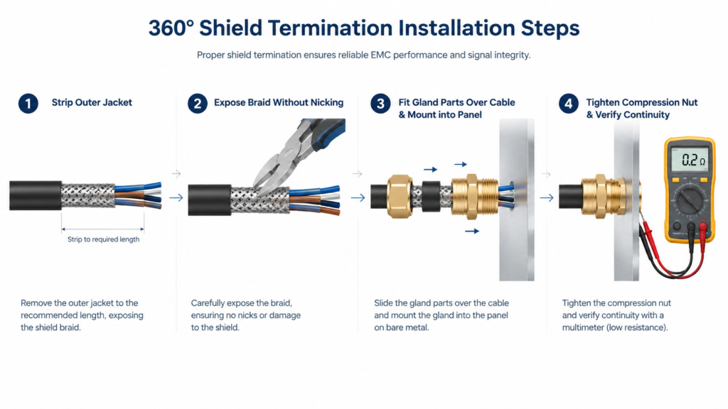
The gland can only ground the shield if the enclosure itself is grounded and the gland-to-panel interface is conductive. Three panel-side details cause most “no ground” callbacks:
When the panel is grounded and the gland sits on bare metal, the shield current flows through the gland body to the cabinet earth — the bond you are trying to create.
| Mistake | Symptom | Fix |
|---|---|---|
| Contact clamped on the jacket, not the braid | Continuity test fails between shield and gland | Re-strip the cable with the correct strip length and reposition the contact over the exposed shield |
| Painted or coated panel | Gland tests fine alone but not against the cabinet earth | Prepare bare metal at the hole or use a serrated EMC locknut |
| Over-tightening the compression nut | Deformed contact elements, crushed shield, intermittent continuity | Tighten to the rated torque; do not pull or rotate the cable afterwards |
| Damaged braid from careless stripping | Weak or broken shield strands, higher resistance | Use a sharp blade, strip in one controlled cut, and inspect the braid before assembly |
| Missing or loose locknut | Gland can rotate, seal relaxes, continuity is intermittent | Fit the locknut and tighten it against the panel from inside |
| Relying on a long pigtail instead of the gland | Noise problems return above a few MHz | Terminate the shield 360° at the entry; use drain wires only for low-frequency signals |
EMC cable gland grounding is straightforward when the fundamentals are respected: expose the braid, clamp it with full 360° metal contact, seat the gland on bare grounded metal, and verify the bond with a continuity test. The shield then does its job — carrying interference to ground at the enclosure wall instead of letting it into your circuits.
If you are unsure which gland series, thread or seal material fits your cable and environment, our engineers can help you select the right EMC cable gland for your application. Contact us with your cable details and enclosure configuration.
Not always. For many control and instrumentation loops, the shield is bonded at one end to avoid ground loops. For high-frequency applications such as VFD motor cables, both ends are terminated 360° so the shield carries interference current along the full run. Whichever scheme the design calls for, every point where the shield ends must use a proper gland bond — never a floating shield.
Run a continuity test. With a multimeter on its lowest resistance range, measure between the cable shield and the gland body or enclosure. A solid 360° contact reads close to 0 Ω; an open circuit means the contact element is gripping the jacket instead of the braid.
No. Paint and powder coating are insulators. Prepare bare metal at the mounting hole or use an EMC/serrated locknut that bites through the coating, otherwise the gland body is electrically isolated from the grounded panel.
A 360° termination clamps the braid around its full circumference directly to the gland, creating a low-impedance path to ground. A pigtail twists the braid into a wire tail, adding inductance that degrades shielding at higher frequencies. For EMI-sensitive installations, 360° termination is the reliable method.
Yes. The shielding function and the environmental seal are independent: the seal and O-ring provide the IP rating while the metal contact handles grounding. Choose a gland with the IP rating your environment needs, and make sure every sealing element is compressed during installation.
An EMC locknut is recommended where electrical continuity matters. It secures the gland mechanically and maintains the earthing/shielding contact between the gland body and the panel. A standard locknut holds the gland in place but may not guarantee a conductive interface on coated panels.
A practical guide to cable gland torque specifications and sealing points, covering nylon, brass, and stainless steel torque values by thread size.
Read More
JIXIANG explosion proof cable glands are designed for hazardous and explosive environments where maximum safety is required. Our EX cable glands comply with ATEX and international explosion-proof standards, ensuring reliable cable sealing and grounding in oil & gas, chemical, and industrial applications. Product Types Single seal explosion-proof cable gland Double seal armored cable gland (CW […]
Read More
Compare metric, PG, and NPT cable gland sizes in one chart. Learn how to measure cable diameter, match sealing ranges, and avoid sizing mistakes.
Read More