Blog
Cable Gland Torque Specifications and Sealing Points Guide
A practical guide to cable gland torque specifications and sealing points, covering nylon, brass, and stainless steel torque values by thread size.
Read More
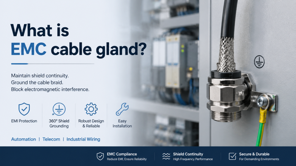
An EMC cable gland is a cable entry device that does more than seal and secure a cable: it keeps the cable’s shield electrically bonded to the enclosure, so electromagnetic interference (EMI) is diverted to ground instead of disturbing sensitive circuits. Standard glands stop dust and water, but they do not maintain shielding continuity. EMC glands add a conductive contact element that grips the cable’s braided shield and ties it to the grounded enclosure. This guide explains what an EMC cable gland is, how it works, why it matters, and how to install one correctly.
EMC stands for Electromagnetic Compatibility — the ability of electrical equipment to function satisfactorily in its electromagnetic environment without introducing intolerable disturbances to other equipment. An EMC cable gland is a specialized cable entry device that supports this goal by maintaining the continuity of a shielded cable’s screen through the point where the cable enters an enclosure.
Unlike a standard cable gland, which focuses on mechanical clamping and environmental sealing, an EMC cable gland adds two functions:
In practical terms, the gland acts like part of a Faraday cage: interference is carried along the shield and safely routed to ground at the enclosure wall, instead of radiating into the panel or coupling into the cable core.
The cable entry point is one of the weakest links in any shielding scheme. A shielded cable running into an enclosure is only as good as the connection at its end. If the shield stops at the gland without a conductive bond, it can act like an antenna — picking up external noise and radiating it into the enclosure, or emitting noise from the circuits inside.
EMC cable glands prevent this by ensuring the shield remains connected to the enclosure’s ground reference. That matters in installations where sensitive equipment shares space with motors, drives, inverters, and communication lines:
In these environments, a standard gland that seals well but does not ground the shield can still let EMI degrade signal quality, cause nuisance trips, or fail EMC compliance tests. The EMC gland closes that gap with one component.
An EMC cable gland is built from the same families of parts as a standard gland, plus one critical addition:
Materials follow the same logic as nickel-plated brass cable glands: the body and nuts are nickel-plated brass for conductivity and corrosion resistance; the clamping insert is PA66 nylon for strength and insulation; sealing rings and O-rings are EPDM rubber for environmental sealing. The result is a gland that seals to an IP68 waterproof rating while preserving electrical continuity through the shield.
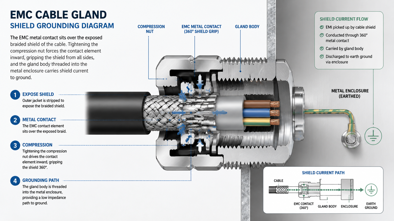
The working principle is straightforward once the shield contact is understood. When a shielded cable enters the gland, the following happens:
Because the contact element adapts to the cable’s outer diameter within the gland’s clamping range and cable OD, one gland model works across a range of cable sizes while maintaining a low-impedance shield connection. The shielding effect is achieved with a single tightening action — no separate grounding wire or disassembly is needed.
The difference between an EMC gland and a standard gland comes down to one question: does the shield stay grounded at the entry point?
| Feature | Standard Cable Gland | EMC Cable Gland |
|---|---|---|
| Strain relief and sealing | Yes | Yes |
| Dust and water protection | Yes (IP rating) | Yes (IP rating) |
| Shield continuity to enclosure | No | Yes — 360-degree conductive contact |
| EMI protection at entry point | Limited | Yes — diverts interference to ground |
| Best fit | General wiring, no shielding requirement | Signal, control, data, and EMC-sensitive installations |
If an installation has no shielded cables and no EMI sensitivity, a standard gland is the economical choice. Where signal integrity or EMC compliance matters — automation panels, telecom, instrumentation, medical, transport — an EMC gland is the correct specification.
Correct installation is what makes an EMC gland actually work. A gland fitted without shield contact is just an expensive standard gland. Follow these steps:
Two common mistakes undermine the shield connection. The first is leaving too much or too little sheath: too much prevents the contact from reaching the braid, too little exposes cable beyond the seal. The second is over-tightening, which can deform the contact elements. Use the gland’s rated torque and verify continuity with a multimeter between the enclosure and the cable shield when the application is critical.
When selecting an EMC cable gland for a project, check four things:
EMC cable glands are available across the common thread standard range, and for most applications the nickel-plated brass version delivers the conductivity and corrosion resistance needed at a reasonable cost.
An EMC cable gland is a standard cable gland plus a conductive shield contact. It seals the cable entry, provides strain relief, and — critically — keeps the cable’s shield bonded to the grounded enclosure so electromagnetic interference is discharged at the wall instead of entering the system. That single function makes it the right choice wherever signal integrity, EMC compliance, or interference rejection matters: automation panels, telecom, instrumentation, medical, transport, and data systems. Match the thread, the cable clamping range, and the IP rating to your installation, and fit the gland so the contact elements grip the exposed shield.
A normal cable gland seals and secures the cable. An EMC cable gland does the same but also maintains a 360-degree conductive contact with the cable’s shield, grounding it to the enclosure to divert electromagnetic interference.
Yes. EMC cable glands combine electromagnetic shielding with environmental sealing, and many models are rated IP68 for dust-tight, continuous-immersion protection. The shielding function and the IP rating are independent — the gland must satisfy both.
The gland contains a conductive metal contact element. When the compression nut is tightened, the element grips the exposed braided shield of the cable, and the gland body — threaded into the metal enclosure — carries the shield current to ground.
If the shielded cable enters a metal enclosure and the installation cares about EMI, yes. Without a bonded shield contact at the entry, the shield can act as an antenna and defeat the purpose of shielding.
Most EMC cable glands use a nickel-plated brass body and nuts for conductivity and corrosion resistance, a PA66 clamping insert for strain relief, and EPDM seals for environmental protection. Stainless steel versions are available for harsher environments.
Generally yes. The compression nut can be opened and the cable removed with the insert, and the gland reinstalled, provided the contact elements and seals are not damaged. Check the gland after each reuse for deformed contacts or worn seals.
A practical guide to cable gland torque specifications and sealing points, covering nylon, brass, and stainless steel torque values by thread size.
Read More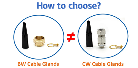
BW and CW cable glands both terminate SWA armoured cable, but they are built for different environments. Learn the key differences, IP ratings, and how to choose.
Read More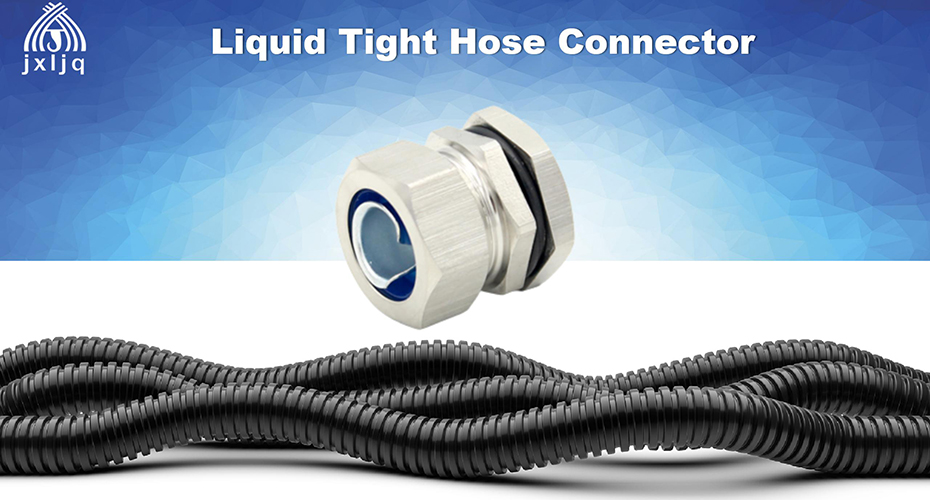
Learn what a liquid tight hose connector does: sealing, strain relief, sizing, installation, and BH vs MH series.
Read More