Blog
Nylon vs Metal Cable Gland A Material Selection Guide
Engineering guide to choosing between nylon, brass, and stainless steel cable glands — environment-driven material selection, side-by-side specs, and a quick selection matrix.
Read More
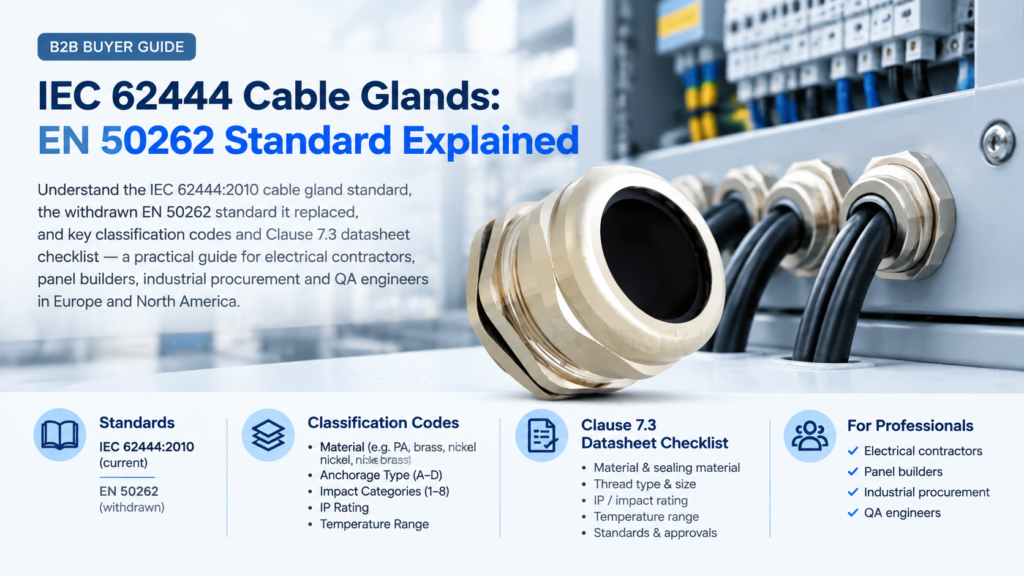
Every cable gland datasheet you receive will name a standard. Most say IEC 62444. Some still say EN 50262. The two lines look interchangeable, and they are not: one of them describes a document that was withdrawn over a decade ago. Knowing which is which, and what the codes that follow the standard number actually mean, is the difference between a specification that survives a project audit and one that quietly fails it. This guide walks through IEC 62444 clause by clause, explains what replaced EN 50262 and when, and gives you a datasheet checklist you can run against any cable glands offer before you commit to an order.
IEC 62444:2010, Cable glands for electrical installations, was published in August 2010 by IEC technical committee TC 23/SC 23A (Cable management systems). It sets out requirements and test methods for the construction and performance of cable glands: sealing, cable retention, earthing and bonding, impact resistance, corrosion, ingress protection and fire behaviour.
Four scope limits matter more than the rest of the text combined:
| Field | Detail |
|---|---|
| Full title | Cable glands for electrical installations |
| Edition and date | Edition 1.0, published August 2010 |
| Technical committee | IEC TC 23/SC 23A — Cable management systems |
| European equivalent | EN 62444:2013 (IEC 62444:2010, Modified) |
| Replaces | EN 50262:1998 + A1:2001 + A2:2004 |
| Entry thread scope | IEC 60423 metric; Annex A (normative) for NPT |
| Minimum ingress protection | IP54 |
| Minimum temperature range | −20 °C to +65 °C (wider ranges may be declared) |
| Test regime | Type tests on samples, not routine production tests |
EN 50262:1998 was the CENELEC standard for cable glands, titled in most national adoptions as Metric cable glands for electrical installations. It was amended twice, in 2001 and 2004, with a corrigendum in between. Its scope was deliberately narrow: complete metric glands as supplied, not parts; and it explicitly excluded glands for fibre optic cables, glands for mineral insulated cables specified in HD 586, and any gland with a non-metric entry thread.
It also carried a line that tells you how much the discipline has moved. Multi-orifice seals, the standard noted, were “under consideration”.
When IEC 62444 was written, multi-orifice sealing systems were no longer an open question. They are a classification category in their own right, sitting alongside material, mechanical performance, electrical properties and external influences.
| Date | Event |
|---|---|
| 1998–2004 | EN 50262:1998 issued with A1:2001 and A2:2004; harmonised under the Low Voltage Directive 2006/95/EC |
| August 2010 | IEC 62444:2010 published as the international standard |
| 2013 | EN 62444:2013 published as the CENELEC adoption of IEC 62444:2010 (Modified), superseding EN 50262 and its amendments |
| 28 February 2014 | BS EN 62444:2013 supersedes BS EN 50262:1999 in the UK |
| 20 April 2016 | EN 62444:2013 published in the EU Official Journal as a harmonised standard under LVD 2014/35/EU; Directive 2006/95/EC repealed the same day |
| 22 July 2025 | Latest Official Journal reference; EN 62444:2013 remains the current harmonised reference for cable glands under the LVD |
The practical consequence is simple. EN 50262 no longer exists as a route to a presumption of conformity under the Low Voltage Directive. EN 62444:2013 does.
An EN 50262 reference on a 2026 datasheet usually means one of three things, and they are not equally serious:
None of these means the gland is unsafe. It means the evidence trail no longer matches the current harmonised reference, which is precisely what a project QA team, a notified body or an insurer will look at. The fix is the same in every case: ask for a test report that names IEC 62444:2010 or EN 62444:2013 explicitly, together with the testing laboratory, the report date and the sample sizes covered.
If you are building a document pack for a European project, the same request should cover the IP claims. Our guide to IP68 test reports sets out what a defensible immersion report contains and how to spot a self-declared rating.
This is the section most buyers skip, and it is the one that decides whether your specification means anything. The standard is a performance standard: it defines several compliance levels rather than a single pass mark. A datasheet that says only “complies with IEC 62444” has told you almost nothing. What you need is the classification string.
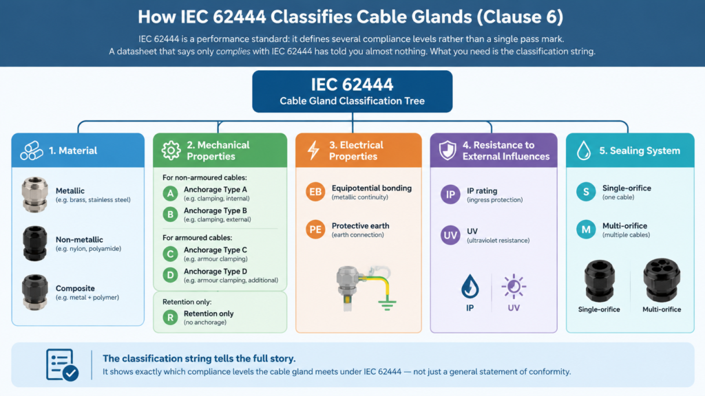
Metallic, non-metallic, or composite. Sealing systems are excluded from the definition, so a brass body with an elastomer seal is still a metallic gland. This matters because several later requirements — corrosion resistance, UV resistance, the electrical current test — attach to specific material classes rather than to all glands.
This is where the standard earns its keep. The two terms it uses are not synonyms:
A gland can be classified for retention only, with no anchorage claimed. The anchorage codes then split by cable construction:
| Classification | Cable type | What is demonstrated |
|---|---|---|
| Retention only | Non-armoured | Holds the cable against a static pull |
| Type A | Non-armoured | Anchorage under pull and twist |
| Type B | Non-armoured | Higher anchorage performance under pull and twist |
| Type C | Armoured | Anchorage including the armour layer |
| Type D | Armoured | Higher anchorage performance including the armour layer |
In selection terms: a retention-only gland is adequate for a fixed, undisturbed entry inside a cabinet. Anything where the cable will be pulled, flexed, vibrated or torqued — a trailing cable on moving equipment, a pendant drop, a machine tool lead — needs an anchorage classification. For armoured cable the choice between Type C and Type D comes down to how much mechanical abuse the installation will see, and it is worth understanding how armoured cable gland types differ before you write the line item.
The standard separates three electrical functions that are routinely blurred together on datasheets:
Electrical current classifications are commonly quoted as class A, B or C. Clause 10.3.2 then verifies the protective earth path with an electrical current test against the values in Table 5. If your installation relies on the gland as part of the earth fault path, this is the clause that decides whether that reliance is justified.
Degree of protection to IEC 60529, and UV resistance. IP54 is the floor set by the standard, not a target. Any figure above IP54 must be declared by the manufacturer and verified under Clause 12.1. When you check a declared rating, check it against the cable diameter range and cut-out dimensions you are actually working with, because the two have to agree — a cable gland size chart is the quickest way to confirm both.
Single-orifice seals, which pass one cable, and multi-orifice seals, which pass several cables through one gland body. The standard treats each alternative sealing arrangement offered for a given gland as a separate sample for testing purposes.
The standard is organised as a test standard. Each clause answers a specific question about the product, and each one produces a number you can put in a specification. Annex B of the standard sets out the order in which the tests are performed.
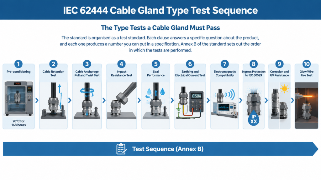
The standard fixes the conditions so that results from different laboratories are comparable. Tests run at an ambient temperature of 20 °C ± 5 °C. Sealing systems are pre-conditioned in an oven at 70 °C ± 2 °C for 168 hours ± 4 hours — and if the manufacturer declares a maximum temperature above 65 °C, the oven is set to that declared temperature plus 5 °C. Samples are then conditioned for at least 24 hours at 20 °C ± 5 °C and 40–60% relative humidity before testing.
Sampling is not one-off. Three samples are tested, and for a gland series the three largest and three smallest sizes are tested along with one sample of every other size in the series. That is the mechanism that stops a supplier from submitting a single favourable size.
A test mandrel matching the minimum value of the declared sealing range is fitted to the gland, and the load from Table 2 is applied. This is the test behind every “pull-out” figure on a datasheet. The result tells you what happens when a cable is tugged statically, for example during a panel build or when a cable bundle is dressed after installation.
Non-armoured glands classified for anchorage are tested under both pull and twist. The pull test applies the Table 2 load to a marked mandrel repeatedly, in the direction of the axis, without jerks, and the displacement is measured against the mark. The twist test applies the torque value from Table 3. Armoured glands are tested separately because the armour layer, not the outer sheath, is the load-bearing element.
This is the distinction that explains why two glands with identical thread sizes and identical sealing ranges can have wildly different service lives on the same machine.
Samples are conditioned at low temperature before the impact is applied at the weakest point of the gland. After the test there must be no disintegration and no visible cracks. The energy applied depends on the category the gland is declared for, and the categories map onto service duty in a way that is directly useful at specification stage.
| Impact category | Energy | Service duty |
|---|---|---|
| 1 to 4 | 0.2 J to 2.0 J | Domestic and commercial |
| 5 | 4.0 J | Light duty industrial |
| 6 and 7 | 7.0 J and 10.0 J | Medium duty industrial |
| 8 | 20.0 J | Heavy duty industrial |
The logical step most datasheets omit: the gland should carry at least the same impact protection as the enclosure it is fitted to. An IP66 enclosure with an IK08 rating protected by a category 4 gland is only as strong as the gland. The IK code system is defined separately in IEC 62262, but the impact energies in IEC 62444 Table 4 cover the same ground and then some.
Seal performance is tested after the mechanical tests, on the same samples, because a gland that leaks after being pulled and struck is not a sealed gland. The IP verification itself is performed to IEC 60529, split into protection against solid foreign objects and protection against water ingress. This is the clause that turns an IP68 claim into a tested statement rather than a badge.
Equipotential bonding to the equipment, equipotential bonding to the cable’s metallic layer, and the protective earth connection are each verified. The electrical current test in 10.3.2 applies the current values from Table 5 through the protective earth path. For glands on armoured or screened cable, this is the test that proves the armour or screen actually forms a continuous earth path through the gland body.
EMC behaviour is addressed as part of the standard rather than left to the market. Where a gland is declared for EMC performance, this is the clause that governs it.
Metallic parts must be resistant to, or protected against, corrosion under Clause 8.6, and this is verified under 12.2. UV resistance is verified under 12.3 for glands declared against 6.4.3.2. Corrosion test methods commonly reference ISO 9227 salt spray. For coastal, marine and outdoor installations this is the clause to look at, and it is one reason material selection matters more than IP rating alone.
Reaction to fire is assessed with a glow-wire test, typically at 650 °C, with acceptance based on the absence of flame or glowing, or extinction within a defined period. Resistance to fire is addressed separately. For glands on cable penetrating a fire-rated compartment, this is the clause that supports the claim.
Clause 7.3 is the most immediately useful part of the standard for a buyer, because it lists the information the manufacturer or supplier must publish. If any of these eleven items is missing from the datasheet you were sent, the documentation is incomplete — regardless of how the product performs.
| # | Required information | Why it matters to you |
|---|---|---|
| 1 | Sealing range (minimum and maximum cable dimensions) | The single most common cause of field sealing failure is a cable outside the declared range |
| 2 | Installation torque, if any | Over-torquing damages the seal; under-torquing leaves the IP rating untested in practice |
| 3 | Entry thread length, if any | Determines whether the gland seats fully in a thick enclosure wall or gland plate |
| 4 | Entry thread size and type | Metric, PG, NPT and other forms are not interchangeable without adaptors |
| 5 | Maximum clearance hole diameter | Governs the cut-out, and a loose cut-out voids the seal no matter how good the gland is |
| 6 | Type of cable anchorage and anchorage range, if any | Tells you whether you are buying retention only, Type A/B or Type C/D |
| 7 | Impact category | Matches the gland to the mechanical duty of the installation |
| 8 | Correct assembly for use as part of the protective earth conductor or electrical connection | Assembly order determines whether the earth path is continuous |
| 9 | Degree of protection to IEC 60529, if higher than IP54 | An undeclared IP means the default IP54 applies |
| 10 | Temperature range, if different from the standard minimum | Required for high-temperature or cold-store installations |
| 11 | Multi-orifice seals, if any | Multi-hole seals need a separate sealing range per orifice |
Two adjacent requirements reinforce the list. Clause 7.1 covers marking, and Clause 7.2 covers its durability: the marking is rubbed by hand for 15 seconds with a cloth soaked in water, then for 15 seconds with a cloth soaked in petroleum spirit, and must remain legible afterwards. A gland whose size and thread marking rubs off during installation is not a compliant gland.
In practice, the installation torque figure in item 2 is where specifications most often go wrong. If you want the reasoning behind torque values and where the sealing interface actually sits, our guide to installation torque covers it in detail.
Being clear about the edges of the standard is as useful as knowing what is inside it. The standard does not:
The same logic applies on the other side of the Atlantic. North American projects work to a different framework, and a gland that satisfies IEC 62444 is not automatically acceptable there — the differences are set out in our guide to UL 514B for North America.
A specification that says “cable gland to IEC 62444” transfers all the risk to you. A specification that states the classification does the opposite. A workable line reads like this:
Cable gland, metallic, nickel-plated brass, M20 × 1.5 metric entry thread to IEC 60423. IEC 62444:2010 classification: anchorage Type A for non-armoured cable, impact category 5, degree of protection IP68, temperature range −40 °C to +100 °C, protective earth connection verified to Clause 10.3.2. Sealing range to be stated and to bracket the measured cable outside diameter.
Four elements in that sentence are doing real work. The thread standard fixes the mechanical interface. The anchorage type fixes the mechanical duty. The impact category fixes the abuse the gland must survive. The sealing range forces the supplier to commit to a number you can check against your cable. Everything else on the datasheet is supporting evidence.
Two more fields are worth adding for outdoor or process installations: the declared UV resistance if the gland will be exposed, and the corrosion protection method for the metallic parts.
| Misunderstanding | What the standard actually says |
|---|---|
| “IEC 62444 compliance is pass or fail” | It is a performance standard with selectable levels. The classification string is the substance |
| “EN 50262 and EN 62444 are equivalent” | EN 50262 was withdrawn; EN 62444:2013 replaced it and is the current harmonised reference under the LVD |
| “IP68 is the top of the standard” | The standard sets IP54 as the floor. Any higher figure is a manufacturer declaration verified under Clause 12.1 |
| “Certification means every unit is tested” | All tests are type tests on samples drawn from a series |
| “The gland rating sets the assembly rating” | The assembly is limited by its weakest element, including the cut-out and gasket |
| “A high impact category covers hazardous areas” | Hazardous area use requires the IEC 60079 series in addition to IEC 62444 |
| “Thread size is enough to order” | Sealing range, anchorage type and impact category are equally load-bearing |
The standard does two things at once. It replaced a narrower European standard with a global one that covers metric and NPT threads, adds multi-orifice seals and standardises the test methods. And it converted “is this gland compliant?” into a set of numbers you can specify: material class, anchorage type, impact category, IP level, temperature range and electrical classification.
The three habits worth taking away are these. Ask for a test report that names IEC 62444:2010 or EN 62444:2013 explicitly, and treat a lingering EN 50262 reference as a documentation question to resolve rather than a reason to reject. Write the classification string into the specification instead of the standard number alone. And run the eleven Clause 7.3 items against every datasheet you receive, because a datasheet that omits the sealing range or the clearance hole diameter has not told you what you are buying.
If you are working through a specification and want a second opinion on the classification you need, contact us with your cable outside diameter, enclosure thread and the environment the entry sits in, and we will map it to the right gland.
No. EN 50262:1998 and its amendments were superseded by EN 62444:2013, which is the CENELEC adoption of IEC 62444:2010. EN 62444:2013 is the standard currently referenced in the EU Official Journal as harmonised under the Low Voltage Directive 2014/35/EU. If a datasheet still cites EN 50262, ask for the current test report.
Retention limits displacement of the installed cable under static load. Anchorage limits displacement under dynamic and torque loads. IEC 62444 classifies anchorage as Type A or B for non-armoured cable and Type C or D for armoured cable, and permits a gland to be classified for retention alone.
IP54. Clause 8.4 requires a minimum degree of protection of IP54 to IEC 60529, and Clause 7.3 requires the manufacturer to declare the IP rating whenever it is higher than IP54.
Not on its own. The standard covers construction and performance for general electrical installations. Glands used in explosive atmospheres must also meet the IEC 60079 series, including IEC 60079-0 for general requirements and the relevant protection concept such as IEC 60079-7 for Ex e or IEC 60079-31 for Ex t.
Clause 8.5 requires suitability for at least −20 °C to at least +65 °C. A wider range can be declared by the manufacturer, and when the declared maximum exceeds 65 °C the pre-conditioning oven is set to the declared temperature plus 5 °C.
Three samples are tested. For a gland series, the three largest and three smallest sizes are tested, along with one sample of every other size in the same series. Where a gland offers alternative sealing arrangements, each arrangement counts as a separate sample.
Clause 7.3 requires the sealing range, installation torque if any, entry thread length and size and type, maximum clearance hole diameter, cable anchorage type and range, impact category, correct assembly for protective earth use, the IP rating if above IP54, the temperature range if different from the standard, and details of any multi-orifice seals.
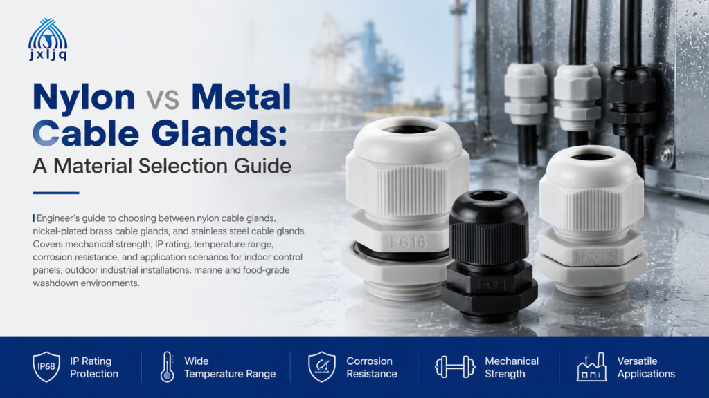
Engineering guide to choosing between nylon, brass, and stainless steel cable glands — environment-driven material selection, side-by-side specs, and a quick selection matrix.
Read More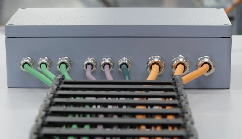
Introduction: Why Material Selection Matters in Cable Glands Choosing between a brass cable gland and a stainless steel cable gland is not just a cost decision. It directly affects long-term sealing reliability, corrosion resistance, and system safety in industrial electrical installations. In real-world projects, many failures do not come from the cable gland design itself, […]
Read More
A marine cable gland is a sealing device used for cable entry in industrial electrical installations, shaped like a sleeve. When a cable passes through the gland, epoxy glue or a compression seal is used to achieve explosion-proof, waterproof, and dust-proof sealing at the enclosure entry point. On a ship, every cable that passes through […]
Read More