Blog
Nylon vs Metal Cable Gland A Material Selection Guide
Engineering guide to choosing between nylon, brass, and stainless steel cable glands — environment-driven material selection, side-by-side specs, and a quick selection matrix.
Read More
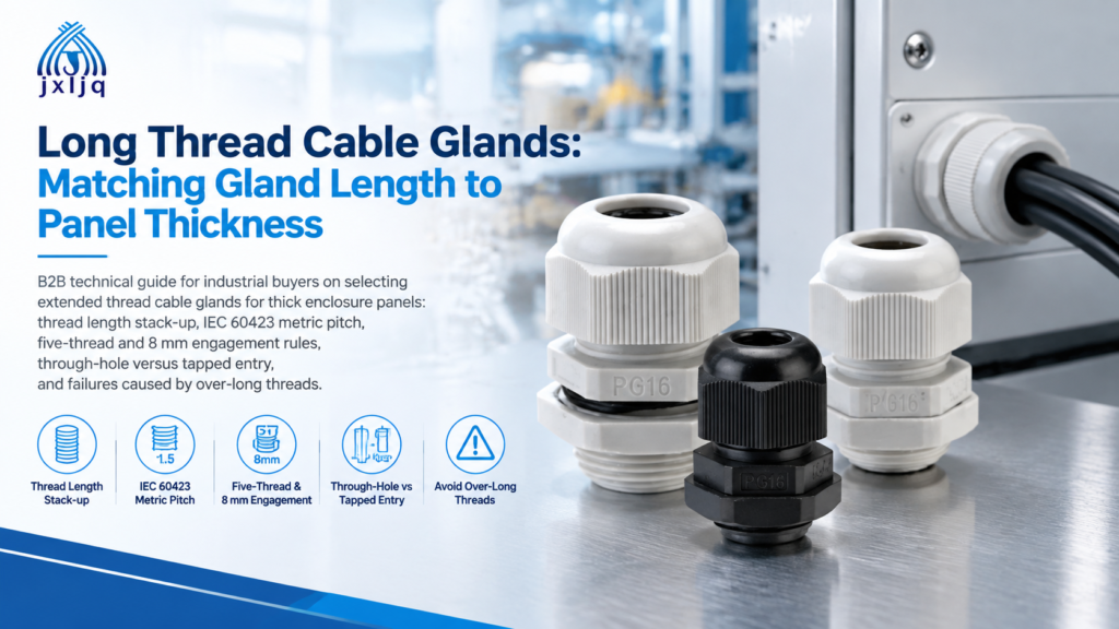
A 12 mm cast aluminium enclosure, an M20 entry and a standard gland with an 8 mm thread. The gland goes in, the sealing washer sits flat, and the locknut on the inside catches about two turns before it runs out of thread. It feels tight with a spanner, so it passes the visual check. Six months later the entry weeps.
That gap between “it threaded on” and “it is properly clamped” is where most thick-panel sealing failures start. A long thread cable gland exists to close it, but only if the thread length is matched to the actual panel stack rather than guessed from the enclosure’s nominal wall thickness.
This guide gives you the arithmetic, the two different calculations that apply to through-holes and tapped entries, the engagement figures that standards actually require, and the four ways an over-long thread causes its own problems.
You need one when the thread cannot reach through the wall and still leave the locknut fully engaged. In practice that happens in three situations:
| Situation | Why the standard gland fails | What fixes it |
|---|---|---|
| Wall thicker than the entry thread | Locknut has only 1–3 turns of grip, or cannot start at all | Extended thread length gland |
| Wall plus washer plus locknut exceeds the thread | Locknut seats on the last partial thread and loosens under vibration | Extended thread, or a low-profile locknut plus a thinner washer |
| Blind tapped boss deeper than the thread is long | Not a length problem in the usual sense — but a long thread can bottom out before the shoulder seats | Correct thread length, not more of it |
The important thing to notice is the third row. Thick wall does not automatically mean longer thread. It means you have to know which of the two joint types you are installing into, because they are calculated differently.
Published catalogue data makes the scale of the problem concrete. In one common European range, standard entry threads run 6 mm on M12, 7 mm on M16, 8 mm on M20 and M25, 9 mm on M32 to M50, and 14 mm on M63. The extended versions of the same range run 12 mm on M12 to M25, 15 mm on M32 to M50, and 18 mm on M63. So on an M20 entry, “standard” gives you 8 mm of thread to pass through a wall, a washer and a locknut. On a 10 mm panel there is nothing left.
Selecting a long thread cable gland is not a single measurement against a single wall thickness. It is a stack-up, and every layer in the stack consumes thread.
Add them and you have the minimum thread length for a through-hole installation:
Required thread length = panel thickness + washer thickness + locknut height + (2 × thread pitch)
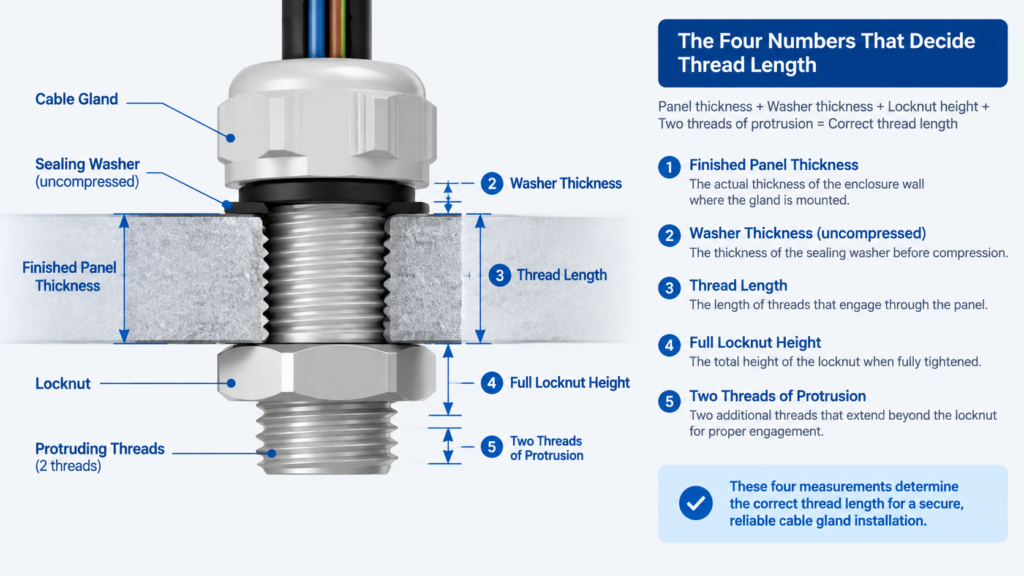
A worked case: 10 mm panel, 1.5 mm washer, 5 mm locknut, M20 × 1.5 thread. Required length = 10 + 1.5 + 5 + 3 = 19.5 mm. An 8 mm standard thread is 11.5 mm short. A 12 mm extended thread is still 7.5 mm short. You need a gland with roughly 20 mm of thread, or a change of approach.
That is the point at which a long thread cable gland stops being optional. This is also the calculation most selection guides skip. They compare thread length to wall thickness alone and conclude that a 12 mm extended thread covers a 12 mm wall — ignoring that the locknut and washer have to fit in the same thread length.
These are genuinely different joints, and mixing up the arithmetic is the second most common reason a long thread cable gland is ordered in the wrong length — after ignoring the locknut.
| Through-hole with locknut | Tapped (threaded) entry | |
|---|---|---|
| How it seals | Sealing washer compressed between gland shoulder and panel face; locknut clamps from the inside | Washer or O-ring compressed against the boss face; thread carries the load |
| What the thread must do | Pass through the wall and carry the full locknut height | Engage the tapped thread by the required depth without bottoming out |
| Sizing rule | Panel + washer + locknut + 2 threads | Engagement depth required by the standard, plus clearance so the shoulder seats |
| Failure if too short | Locknut hangs on partial threads and loosens | Insufficient flame path or thread strength; joint not certified |
| Failure if too long | Excess thread protrudes inside the enclosure | Gland bottoms out in a blind boss; shoulder never seats; washer never compresses |
For a tapped entry the thread length you need is roughly the boss depth you intend to use plus a millimetre or two of margin. More thread than the boss is deep is not a safety factor — it is a leak waiting to happen, because the gland stops turning on the bottom of the hole while the shoulder is still 3 mm off the face.
This is where published guidance diverges, so it is worth being precise about what each standard does and does not say.
Two practical consequences follow. First, on an IP-only job you cannot cite a standard to justify two threads of locknut grip — you are relying on the manufacturer’s instruction, so read it. Second, thread sealant is not a substitute for engagement. PTFE tape or liquid sealant applied to make up for a short thread does not create a certified flame path, and on a through-hole joint it does not compress the washer either.
The examples below use the through-hole formula. Substitute your own washer and locknut dimensions; the structure of the calculation does not change.
Standard gland, locknut on the inside. Required length = 1.5 + 1.5 + 5 + 3 = 11 mm. An 8 mm standard thread is short, but the locknut sits inside a thin wall where the panel itself is the only obstacle, and a standard gland plus locknut is the normal, correct answer here. Watch the paint: the sealing washer must sit on bare, flat metal, so mask the entry face before coating or fit a serrated washer to bite through.
Required length = 6 + 1.5 + 5 + 3 = 15.5 mm. This is the crossover point. A standard 8 mm thread leaves the locknut hanging; a 12 mm extended thread gives you 4.5 mm less than the calculation wants but works if you use a low-profile locknut. The clean answer is a 15–16 mm thread, or a standard gland with a mounting plate that brings the entry face forward.
Required length = 12 + 1.5 + 5 + 3 = 21.5 mm. This is squarely long-thread territory. Note that cast walls are not uniform — measure at the entry, because a boss may be 12 mm while the surrounding wall is 8 mm, or the reverse.
Required length = 50 + 1.5 + 5 + 3 = 59.5 mm. No standard catalogue gland reaches this, and a custom thread of 60 mm on an M20 body is a poor engineering answer: the gland body would sit 60 mm off the wall, creating a long lever arm on a foam-cored panel that has almost no local stiffness. The right solution is a gland plate or a short through-bulkhead nipple that bridges the panel and gives the gland a rigid, flat face to seal against. Treat the sandwich panel as an enclosure problem, not a gland problem.
Use this cable gland panel thickness table as a starting point for through-hole installations, then confirm against the actual drawing. The thread length column assumes a standard 5 mm locknut, a 1.5 mm washer and two protruding threads.
| Panel thickness | Typical application | Thread length needed | Practical specification |
|---|---|---|---|
| 1–2 mm | Sheet steel cabinets, plastic boxes | 10–12 mm | Standard gland with locknut on the inside |
| 3–6 mm | Aluminium housings, GRP boxes | 12–16 mm | Standard or short extended thread |
| 7–12 mm | Cast enclosures, machine frames, switchgear | 17–22 mm | Extended thread gland |
| 13–25 mm | Heavy industrial housings, marine castings | 23–35 mm | Extended thread, often custom length |
| 26 mm and above | Sandwich panels, pressure housings | 36 mm and above | Gland plate or through-bulkhead, not a longer thread |
Thread pitch and hole size matter as much as length. Under IEC 60423 the metric conduit thread uses a 1.5 mm pitch from M12 through M75, stepping to 2 mm at M90 and M110, and the clearance hole is nominally the nominal size plus 0.2–0.4 mm. Published installation guidance allows a clearance hole 0.1–0.7 mm larger than the thread’s major diameter. If you are switching thread systems — for example a PG entry being replaced by metric — check the conversion rather than assuming the diameters are close enough; a metric, PG and NPT thread comparison will save you a mis-ordered batch.
| Metric size | Pitch | Nominal clearance hole | 5 threads = | 8 mm rule met by 5 threads? |
|---|---|---|---|---|
| M12 × 1.5 | 1.5 mm | 12.0 mm | 7.5 mm | No |
| M16 × 1.5 | 1.5 mm | 16.0 mm | 7.5 mm | No |
| M20 × 1.5 | 1.5 mm | 20.0 mm | 7.5 mm | No |
| M25 × 1.5 | 1.5 mm | 25.0 mm | 7.5 mm | No |
| M32 × 1.5 | 1.5 mm | 32.0 mm | 7.5 mm | No |
| M40 × 1.5 | 1.5 mm | 40.0 mm | 7.5 mm | No |
| M50 × 1.5 | 1.5 mm | 50.0 mm | 7.5 mm | No |
| M63 × 1.5 | 1.5 mm | 63.0 mm | 7.5 mm | No |
The last column is the point worth carrying into a specification review. At a 1.5 mm pitch, five threads is always 7.5 mm, so on every metric size up to M75 the eight-millimetre clause is the controlling one. A drawing that says “minimum five threads” on an M20 Ex d entry does not meet IEC 60079-1 unless 8 mm is also achieved.
Ordering a long thread cable gland with more thread than the joint needs is not a free safety margin. Four specific problems appear when the thread is longer than the joint is deep.
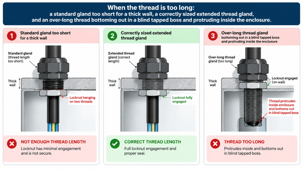
On a tapped entry with a shallow boss, a long thread reaches the bottom of the hole before the shoulder reaches the face. The installer feels resistance, stops, and the sealing washer is never compressed. The joint looks assembled and holds pressure on a bench test with no cable fitted, then leaks in service. If the boss depth is 10 mm, specify roughly 10 mm of usable thread — not 20 mm.
On a through-hole, the extra length ends up inside the box, exactly where the wiring, terminal blocks and DIN rail are. On a small junction box that can block the lid or reduce the wiring space below what the cable needs. It is also a cut hazard during maintenance.
Unused thread is a crevice that holds water and dirt, and the crests are the first thing to be damaged when a gland is knocked or a spanner slips. Damaged thread makes the gland difficult to remove years later, which matters on equipment that will be re-terminated.
Every millimetre of thread between the shoulder and the panel face adds to the cantilever. On a thin or foam-cored panel, that load transfers into a face with very little local stiffness, and the entry starts to work loose under vibration. Long thread is the right answer for a thick, rigid wall — not for a thin wall that happens to have a deep recess.
When a long thread cable gland is not available in the length you need, three routes get you out of the problem, and they are not equivalent.
| Approach | Best for | Trade-off |
|---|---|---|
| Extended thread gland | Wall 7–25 mm, standard thread size, repeatable specification | One part, one seal interface, no added joint |
| Thread adaptor or reducer | Changing thread size or system at an existing entry | Adds a second threaded joint and a second seal interface inside the IP boundary; each joint must be assessed separately |
| Custom thread length | Wall beyond catalogue range, OEM builds, repeat production | Tooling and lead time; worth it when the quantity is real |
The reducer route is the one that gets used too often because it is available off the shelf. It solves a diameter mismatch. It does not solve a length problem, and stacking an adaptor into a shallow entry can make the length problem worse while adding a joint that nobody inspects.
For reference, the two extended-thread series most often specified for this job differ mainly in body material and certification route. The PA66 nylon extended thread gland gives IP68 at 10 bar, −40 °C to +100 °C with 120 °C instant, and is available in metric, PG, G and NPT threads — the usual choice where the enclosure is non-metallic and weight or insulation matters. The nickel-plated brass extended thread gland runs M8 to M100, IP68, −40 °C to +100 °C with 120 °C short-time, with PA claw and NBR seals, and is the choice for cast metal enclosures, marine and offshore work and machinery. Both are offered with custom thread lengths, which is the practical answer when a standard extended thread still falls short of the stack-up.
Thread length is only half of a reliable entry. These eight checks catch the rest.
| Mistake | What actually happens | Correct approach |
|---|---|---|
| Sizing thread to wall thickness only | Locknut and washer have no thread left | Add washer, locknut height and two threads to the wall |
| Using the drawing’s nominal wall | Coating and casting variation consume the margin | Measure the finished wall at the entry, three readings |
| Assuming longer is safer | Blind boss bottoming, internal obstruction, corrosion | Size to the joint, not to a margin |
| Treating a tapped entry like a through-hole | Engagement requirement misapplied; certification issue | Use the tapped-entry rule and the boss depth |
| Specifying “five threads” on M20 Ex d | 7.5 mm is below the 8 mm alternative | Specify 8 mm minimum engagement |
| Stacking a reducer to gain length | Extra joint inside the IP boundary, uninspected | Order the extended or custom thread |
The thread length question has a clean answer once you stop comparing it to wall thickness alone. Measure the finished wall at the entry, add the uncompressed washer, add the full locknut height, add two threads of protrusion, and you have the number to put on the purchase order. Then check which joint you have: a through-hole needs that total, a tapped boss needs the engagement depth plus clearance so the shoulder still seats.
If your cable gland panel thickness falls between roughly 7 and 25 mm and the entry is a standard metric size, an extended thread gland is the direct answer, and a standard gland remains the correct baseline for thin sheet where the locknut sits inside. If the stack-up runs past 25 mm, the enclosure, not the gland, is what needs changing.
Send us the finished wall thickness, the thread specification and the cable outside diameter, and we will confirm the thread length against the drawing before anything is ordered — contact our engineering team with those three numbers and a photo of the entry from both sides.
Measure the finished wall at the entry. If the wall plus the sealing washer plus the locknut height plus two threads of protrusion is longer than the gland’s thread, you need an extended thread. On an M20 entry with a typical 8 mm standard thread, that point arrives at roughly a 4 mm wall once you allow for the nut and washer.
For flameproof Ex d entries, IEC 60079-1 requires five fully engaged threads or 8 mm of axial engagement, whichever is greater. For IP-rated but non-hazardous installations, IEC 60529 does not specify a thread count, so the gland manufacturer’s installation instruction, the washer compression and the applied torque govern.
A reducer changes thread size or thread system. It does not extend thread length, and stacking one into a shallow entry can make seating worse. It also adds a second threaded joint and seal interface inside the IP boundary. Order the extended or custom thread instead.
No. In a blind tapped boss, a thread longer than the usable depth stops the gland before the shoulder seats, so the washer never compresses. In a through-hole, excess thread protrudes inside the enclosure where it obstructs wiring and collects moisture. Size to the stack-up.
With a 1.5 mm washer, a 5 mm locknut and two protruding threads, the calculation is 12 + 1.5 + 5 + 3, so about 21.5 mm of thread. That is beyond most standard extended ranges on small metric sizes, which is why 12 mm walls often need a custom thread length or a larger body size with a longer standard entry.
Indirectly. The IP rating comes from the compressed sealing washer at the shoulder and the cable seal, not from the thread itself. But if the thread is too short for the locknut to clamp the joint, or too long to let the shoulder seat, the washer never reaches its specified compression and the rated protection is not achieved.
Engineering guide to choosing between nylon, brass, and stainless steel cable glands — environment-driven material selection, side-by-side specs, and a quick selection matrix.
Read More
Buying flexible spiral cable glands: what they are, where they are used, the six points to confirm, how to size them, and nylon vs brass selection.
Read More
Introduction In electrical and industrial installations, protecting cables from water, dust, and environmental damage is critical. One of the most commonly used solutions is the IP68 nylon cable gland.This article explains what an IP68 nylon cable gland is, how it works, and why it is widely used in industrial and outdoor applications. What Does IP68 […]
Read More