Why Cable Glands Matter in EV and Energy Storage Infrastructure
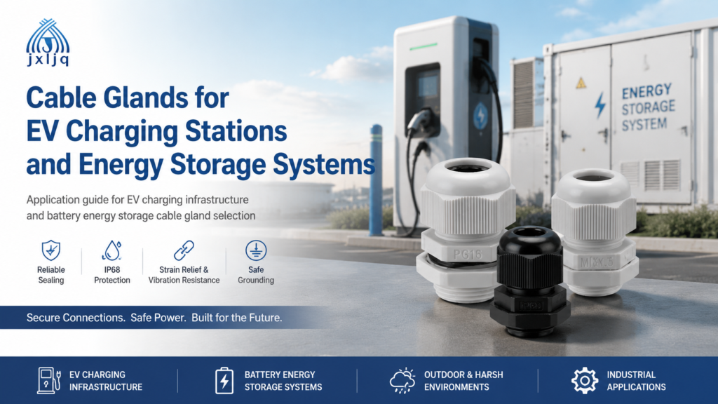
The global shift toward electric vehicles and renewable energy is reshaping electrical infrastructure at every level. By 2030, the International Energy Agency projects more than 300 million EVs on roads worldwide, supported by millions of charging stations and grid-scale battery energy storage systems (ESS). Each of these installations depends on reliable cable management, and at every cable entry point into an enclosure, a cable gland performs the critical work of sealing, securing, and protecting the connection.
In EV charging stations and energy storage cabinets, cable glands are not minor accessories. They maintain ingress protection ratings under daily thermal cycling, resist UV degradation in outdoor installations, provide strain relief for heavy charging cables, and shield sensitive communication lines from electromagnetic interference. When a gland fails, the consequences range from nuisance maintenance calls to safety hazards involving high-voltage DC circuits.
This guide explains how to select and install cable glands for EV charging infrastructure and battery energy storage systems. It covers the specific demands of each application, the technical criteria that matter, and practical recommendations for procurement engineers and system designers.
EV Charging Station Types and Their Cable Entry Requirements
EV charging stations are not a single category. The cable management needs of a residential Level 2 wall box differ significantly from those of a 350 kW DC fast charger or a fleet depot with bidirectional vehicle-to-grid equipment. Understanding these differences is the first step in selecting the right gland.
Level 2 AC Charging Stations
Level 2 stations operate at 208–240 V AC with power outputs from 7.2 kW to 22 kW. These units are common in workplaces, residential complexes, and retail parking. The cable entries are relatively modest: a mains power inlet, an output cable to the vehicle connector, and often a small compartment for control and metering wiring.
For these applications, nylon cable glands in the PG or metric range are typically sufficient for the control and signal cables. The main power cable, especially in outdoor pedestal mounts, benefits from a metal gland with a wider clamping range and stronger strain relief. IP65 is adequate for sheltered locations, but IP66 or IP67 is recommended for fully exposed outdoor installations where rain and dust are constant factors.
DC Fast Charging Stations
DC fast chargers operate at 400 V to 1000 V DC with power levels from 50 kW to over 350 kW. These cabinets are larger, heavier, and far more complex. A typical unit has multiple cable entries: grid supply input, DC output to the charging cable, cooling system lines, communication and payment system wiring, and auxiliary power.
The grid supply cable is often a heavy three-phase conductor with significant weight behind the enclosure. The gland here must clamp firmly enough to support that load without transferring stress to internal terminals. Nickel-plated brass or stainless steel glands are common choices because they resist heat and provide the mechanical strength needed for large-diameter power cables.
The charging cable exit deserves special attention. This is the entry point that takes the most abuse. The cable is pulled, coiled, dragged across concrete, and exposed to UV and ozone daily. A gland with robust strain relief and anti-bending protection prevents flex fatigue from working into the terminals. For high-power cables with large outer diameters, longer thread glands provide deeper engagement with thick enclosure walls.
Charging Cable and Connector Exits
Many modern chargers use modular circular connectors with integrated sealing for the charging cable assembly. Even in these designs, the transition from connector to enclosure wall is a potential failure point. Where a traditional gland is used instead, the clamping range must match the actual cable outer diameter precisely. Undersizing scars the jacket; oversizing leaves the seal uncompressed, creating a path for moisture ingress.
Energy Storage System (ESS) Cable Management Challenges
Battery energy storage systems add another layer of complexity. These installations combine high-voltage DC links, inverter cables, battery management system wiring, and thermal management controls in compact, sealed enclosures. The cable glands must perform under conditions that include thermal cycling, fire safety requirements, and electromagnetic interference.
High-Voltage DC Links and Inverter Cables
Utility-scale ESS containers route hundreds of high-voltage DC cables between battery racks, inverters, and grid connection points. Each penetration through a container wall or switchgear enclosure needs a gland that maintains IP68 sealing while supporting heavy cables. Metal glands with armour clamping functionality are often specified here because they provide grounding continuity for armoured cables and protect sensitive electronics from induced voltages.
In residential and commercial battery packs, space is tighter. Compact polyamide glands with precise clamping ranges fit better in dense enclosures, but they must still meet the same sealing and strain-relief requirements as their industrial counterparts.
Thermal Cycling and Fire Safety
Battery enclosures experience temperature swings with every charge and discharge cycle. These fluctuations cause materials to expand and contract, which can loosen compression seals over time. High-performance glands made from nickel-plated brass or stainless steel maintain clamping integrity through thousands of cycles.
Fire safety is another critical concern. Lithium-ion battery systems carry inherent thermal runaway risk. Cable glands used in ESS applications should comply with flame-retardant standards, and halogen-free sealing materials are increasingly specified to minimize toxic smoke in the event of an incident.
How to Select the Right Cable Gland for EV/ESS Applications
Selecting a cable gland for EV charging or energy storage involves more than matching thread size. Five factors deserve particular attention: ingress protection, material, EMC shielding, thread standards, and sizing.
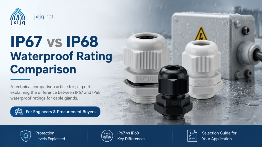
Ingress Protection (IP) Ratings
The IP rating defines how well a gland keeps out solids and liquids. For EV and ESS installations, the following guidance applies:
Application
Minimum IP Rating
Notes
Indoor or sheltered AC chargers
IP65
Dust-tight, protected against water jets
Outdoor exposed charging stations
IP66–IP67
Resists heavy rain and temporary immersion
Underground or submerged entry points
IP68
Continuous immersion protection
High-pressure washdown environments
IP69K
Resists high-temperature, high-pressure jets
Battery storage containers (outdoor)
IP68
Required for condensation and weather exposure
Always confirm the gland rating against the enclosure rating and actual site conditions. A gland with a lower IP rating than the enclosure creates a weak point that compromises the entire system.
Material Selection
The choice between nylon, brass, and stainless steel depends on environment, voltage class, and mechanical demands. Nylon versus metal cable glands each have distinct advantages:
Nylon PA66: Lightweight, non-conductive, and cost-effective. Suitable for indoor AC chargers, control wiring, and low-voltage signal cables. UV-stabilized versions are available for outdoor use, but metal is preferred for extreme heat or heavy mechanical loads.
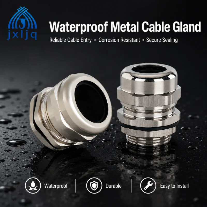
Nickel-plated brass: The industry standard for outdoor power cables. Offers excellent corrosion resistance, high mechanical strength, and good temperature tolerance. Ideal for DC fast charger grid inlets and heavy ESS power cables.
Stainless steel (316/304): Superior corrosion resistance for marine, coastal, or chemically exposed installations. Common in offshore wind-connected ESS and charging stations in harsh climates.
EMC Shielding for Smart Charging
Modern EV chargers are sophisticated electronic systems. They incorporate OCPP communication, smart metering, remote monitoring, and payment processing. High-power switching electronics inside the charger generate electromagnetic interference that can disrupt these signals. EMC cable glands with 360-degree shielding terminate cable braids and maintain grounding continuity, preventing EMI from corrupting data or causing charging errors.
EMC glands are especially important in DC fast chargers and smart grid-connected ESS where communication reliability is non-negotiable.
Thread Standards and Sizing
EV and ESS equipment is sourced globally, so enclosures may use metric (M), PG, NPT, or G threads. Metric threads are the most common internationally, while NPT is standard in North America. When specifying glands, verify the enclosure thread form and match it exactly. Using adaptors is possible but adds potential leak paths; direct-fit glands are preferred for high-IP applications.
Sizing is equally critical. The gland clamping range must center on the cable’s actual outer diameter. Measure with calipers rather than guessing from conductor gauge. A gland sized to the extremes of its range — either too tight or too loose — will fail to seal properly.
Cable Gland Installation Best Practices for Outdoor Charging
Even the best gland will fail if installed incorrectly. For outdoor EV charging and energy storage installations, follow these practices:
Measure cable OD accurately. Use calipers to measure the jacket diameter and select a gland whose clamping range centers on that value.
Seal both sides. Use the manufacturer’s sealing washer under the external locknut or an O-ring under the gland head to close the water path around the threads.
Tighten to specification.Torque the gland to the manufacturer’s rating. Hand-tight plus a guess is not sufficient for thermal cycling environments.
Respect bend radius and strain relief. Avoid sharp bends at the gland entry. Add support clips so the gland does not carry the full cable weight.
Account for thermal cycling. In battery enclosures and high-power chargers, choose materials and seals rated for the full operating temperature range, including worst-case ambient conditions.
Close unused openings. Every knockout or spare entry must be sealed with a rated blanking plug to maintain the enclosure IP rating.
Conclusion
Cable glands are a small component with an outsized impact on the reliability and safety of EV charging stations and battery energy storage systems. The right gland maintains enclosure sealing through years of thermal cycling, supports heavy power cables without transferring stress to terminals, and protects sensitive communication lines from electromagnetic interference.
For procurement engineers and system designers, the selection process comes down to matching the gland’s IP rating, material, clamping range, and thread form to the actual installation environment. Treat cable glands as part of the enclosure design from the start, not as an afterthought. The result is infrastructure that lasts — and stays safe.
If you are specifying cable glands for a new EV charging or energy storage project, explore our longer-thread nylon cable glands for deep enclosure walls, or browse our full range of waterproof connectors for industrial and new energy applications.
Frequently Asked Questions (FAQ)
What IP rating do I need for an outdoor EV charging station?
For exposed outdoor locations, IP66 or IP67 is the minimum recommended rating. IP68 is preferred for ground-level installations or areas subject to flooding. IP65 may suffice only for fully sheltered indoor or carport locations.
Can nylon cable glands be used in EV charging applications?
Yes, for control wiring, metering enclosures, and light-duty AC chargers. For main power inlets, DC fast chargers, and heavy ESS cables, metal glands provide better mechanical strength, heat resistance, and strain relief.
Why are EMC cable glands important for EV chargers?
Modern chargers contain high-frequency power electronics that generate electromagnetic interference. EMC glands terminate cable shields and maintain grounding continuity, preventing EMI from disrupting communication, metering, and payment systems.
What thread standard is most common for EV charging enclosures?
Metric (M) threads are the global standard for most industrial enclosures. North American installations may use NPT. Always verify the enclosure thread before ordering glands.
How do I size a cable gland for a large EV charging power cable?
Measure the cable’s actual outer diameter with calipers, then select a gland whose clamping range centers on that measurement. Do not size based on conductor gauge alone. For thick enclosure walls, consider longer-thread glands to ensure full thread engagement.
Are special cable glands required for battery energy storage systems?
ESS applications often require IP68 sealing, flame-retardant materials, and EMC shielding. Metal glands are preferred for high-voltage DC links, while compact nylon glands may suit control and BMS wiring in space-constrained residential units.
A practical guide to cable gland sealing ranges: measure cable outer diameter correctly, match it to the right gland size, and avoid sealing failures in industrial installations.
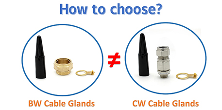
BW and CW cable glands both terminate SWA armoured cable, but they are built for different environments. Learn the key differences, IP ratings, and how to choose.
We use cookies to enhance your browsing experience, serve personalised ads or content, and analyse our traffic. By clicking "Accept All", you consent to our use of cookies.