Blog
Cable Gland Terminology: Raccord Étanche, Prensacables IP68
Cable gland terminology in French, Spanish, Portuguese, German and Italian — which words translate, which thread and IP codes never do, and a bilingual RFQ block.
Read More
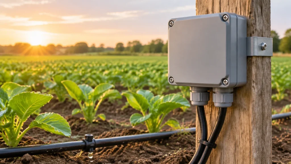
An irrigation junction box is usually blamed for a fault that started somewhere else. The box fills with water, the zone stops firing, and the enclosure gets replaced — then the new one fails the same way three seasons later. In field wiring the box is rarely the weak point. What actually decides whether a zone opens on command is the number of cable entries the enclosure can accept, the volt drop on a 24 VAC circuit that nobody calculated, the fact that a valve box is designed to drain rather than to seal, and condensation inside a box that is sealed properly. Get those four right and the choice of enclosure becomes straightforward; get them wrong and no IP number will save the circuit.
Agricultural irrigation is a low-voltage, long-run, high-moisture system. The conductors are small, the runs are hundreds of metres, and the enclosure usually sits at the lowest, wettest point of the property. Most published guidance stops at “use a waterproof connector”, which is correct but incomplete: a perfectly sealed splice still fails if the controller cannot deliver enough voltage to pull the solenoid in, and a sealed box bolted to a post in full sun still fills with condensate. Work through the four constraints in order and the enclosure choice follows.
Count conductors before you look at a catalogue. A conventional system runs one switched conductor per zone plus a shared common, so a six-zone manifold arrives at the box as seven conductors, and a system with spares as nine or ten. That number is the real sizing input, because each cable needs its own entry and each entry is a seal.
| Zones at the box | Conductors | Typical arrangement |
|---|---|---|
| 1 | 2 | Single splice, mini box with two openings |
| 4 | 5 (+1–2 spare) | Multi-core cable into a cabinet, or four separate splices |
| 8 | 9 (+2 spare) | Field cabinet with glands and a terminal strip |
| 16+ on a two-wire decoder system | 2 | Two conductors regardless of zone count |
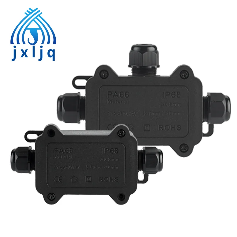
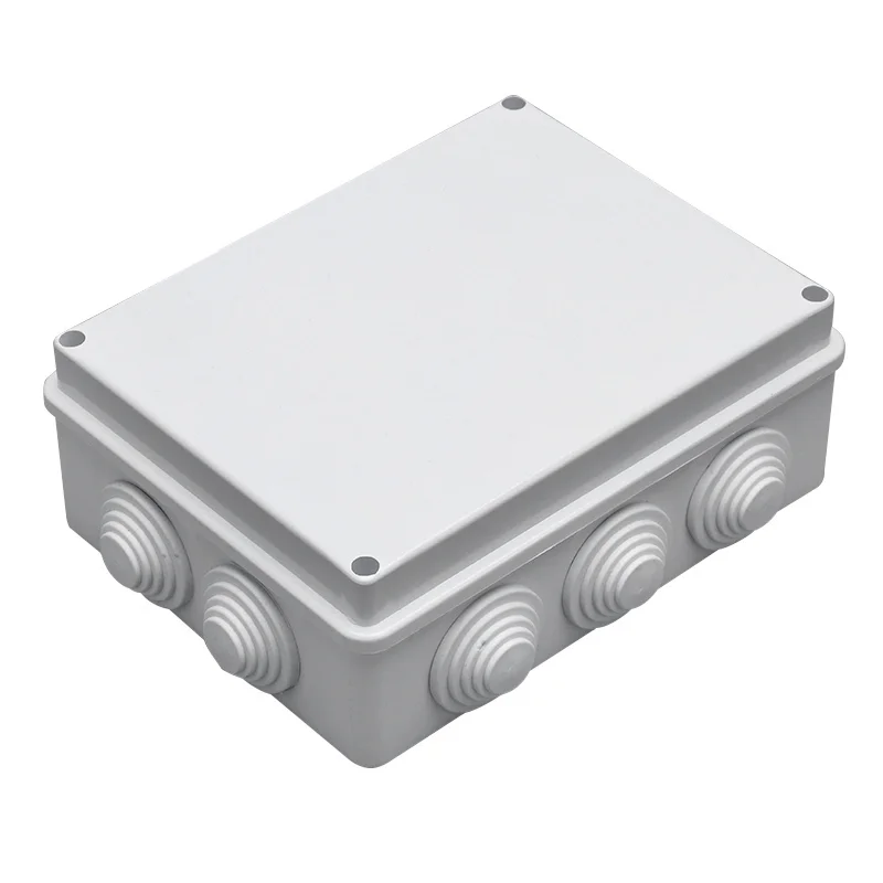
This is where compact splice boxes run out of road. A mini junction box like our F1 range has two, three or four openings, and each opening feeds one pole pair — it is a single-circuit device. It is excellent for one splice in a wet place and the wrong product for distributing seven conductors, no matter how good its IP rating is. Anything above a single circuit needs a cabinet with individual glands and a terminal strip, and the entry count then drives the enclosure size more than the cable volume does. The arithmetic is the same one covered in how many cables one junction box can take.
A 24 VAC solenoid is a picky load. It needs roughly its rated voltage to pull in, and controllers are usually specified to hold within ±10%, so the budget from 24 V to the solenoid is about 2.4 V. On a 200 m run that budget disappears quickly, and it disappears on the common conductor as well as the switched one — the current flows out and back, so the loop length is twice the one-way distance.
| Cable | Loop resistance per 100 m | Drop at 100 m | Drop at 200 m | One-way run on a 2.4 V budget |
|---|---|---|---|---|
| 18 AWG | 4.19 Ω | 1.47 V | 2.93 V | about 160 m |
| 16 AWG | 2.63 Ω | 0.92 V | 1.84 V | about 260 m |
| 14 AWG | 1.66 Ω | 0.58 V | 1.16 V | about 410 m |
| 12 AWG | 1.04 Ω | 0.36 V | 0.73 V | about 660 m |
The figures assume 0.35 A holding current and a resistive estimate; a solenoid is an inductive load, so the true steady-state drop is usually a little lower and the inrush a lot higher. Treat the table as a screening tool, then confirm against the solenoid’s minimum operating voltage. The practical consequence for the box is indirect but real: undersized cable is often “fixed” in the field by doubling conductors, which doubles the entry count at the very enclosure that had no spare openings.
Most systems share one common return across every valve, which is efficient until a master valve or pump relay runs with a zone. Then the common carries the sum of both currents while each switched conductor carries one. The result is an asymmetric drop: the zone wire looks fine on a meter and the valve still chatters, because the loss is on the return path. Size the common for the worst simultaneous pair, not for a single valve, and never reduce it because “it is only the return”.
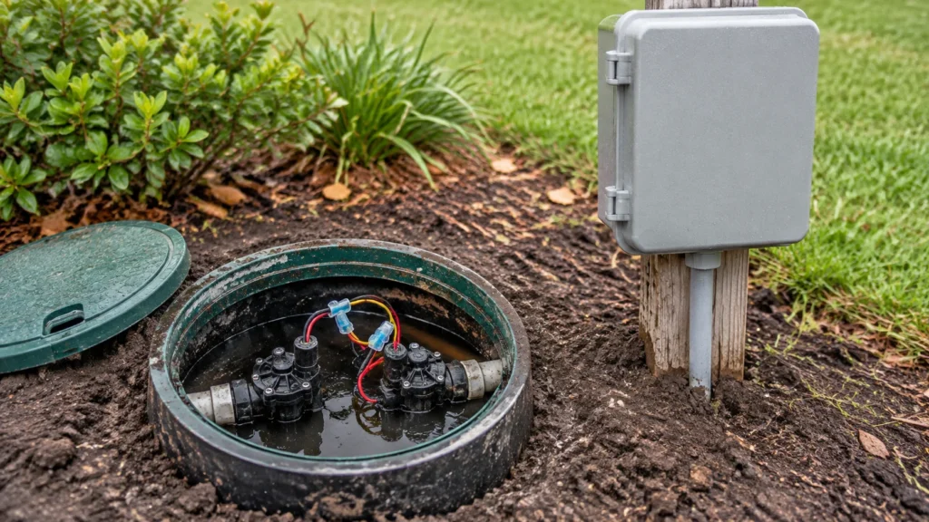
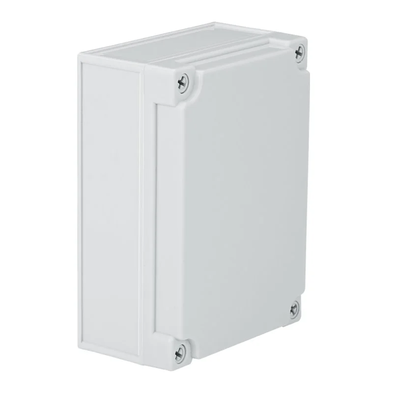
These three locations have different jobs and should not be sealed the same way. A valve box is an open-bottomed pit: it drains, it collects soil, and it floods during irrigation. Making one watertight is wasted effort, so splices inside it belong in gel-filled connectors that tolerate standing water. A field cabinet is the opposite problem — a closed volume that must stay dry, so it needs glands, a drip loop and a vent. A box on a riser above grade sits between the two: exposed to sun and mowers, but draining freely, so the entry seals do the work. Sealing an enclosure at the bottom of a flooded pit is the most common specification error we see on agricultural projects.
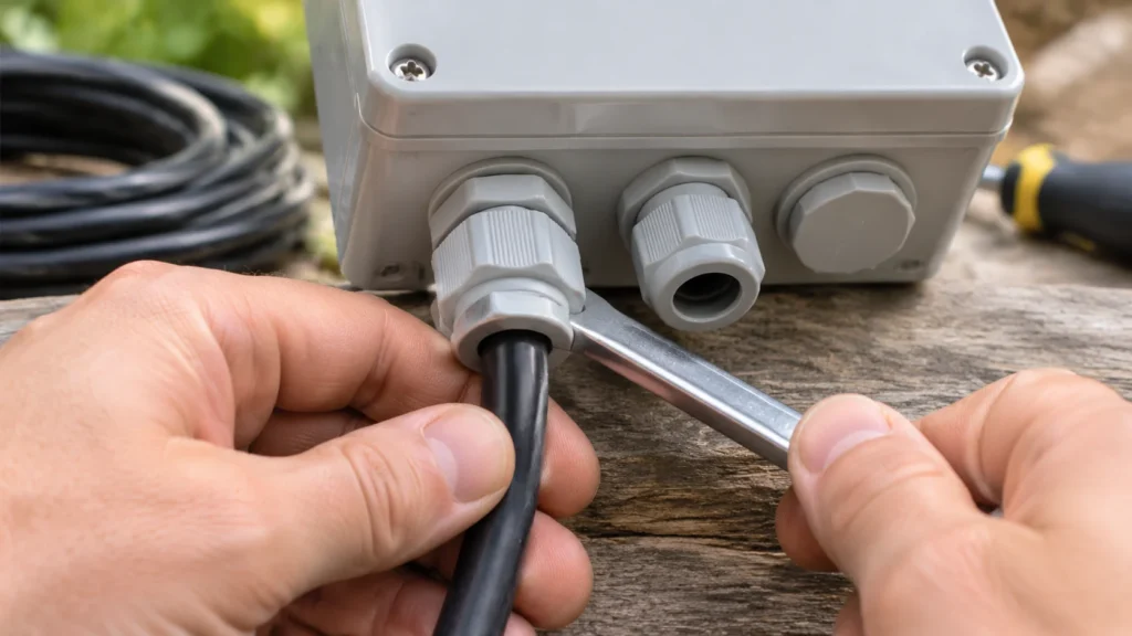
Every entry is a seal, and a seal is rubber compressed around a jacket. Two cables forced through one gland never compress evenly — the stack forms an oval and water follows the gap. Fit one cable per gland, match the gland to the measured jacket diameter, and leave 1–2 spare conductors per run so a future zone does not need re-trenching. Leave a service loop long enough to re-terminate twice, and clamp the cable outside so soil movement loads the clamp rather than the terminal.
Ultraviolet exposure is a materials question, not a coating: a polyamide or ABS housing stabilised for outdoor use holds its impact strength for years, while an unstabilised one goes chalky in a couple of seasons. Frost is the opposite failure — water trapped in a gland expands and splits the seal, which is why every run enters from below. Rodents attack the cable jacket rather than the enclosure; mowers attack the box itself, which argues for a riser rather than a grade-level lid.
A sealed box in an irrigated field breathes twice a day. Warm humid air enters whenever the enclosure is opened or the glands relax, then the night drop brings every internal surface below the dew point and the water lands on the terminals. The tell is a box that is bone dry outside and wet inside. A breathable vent equalises pressure without admitting liquid water, which is the fix; more sealant is not. The physics and the repair sequence are set out in condensation in junction boxes, and the component is the breathable vent plug.
| Parameter | F1 series | JX-AG series |
|---|---|---|
| Protection | IP68 | IP67, immersion to 1 m |
| Impact | Not declared | IK08 |
| Cable range | 3–10 mm, in three ranges | By gland selection |
| Conductors | 0.5–4 mm² (2-way), 0.5–2.5 mm² (3- and 4-way) | Terminal dependent |
| Rating | 450 V, 16 A or 24 A | Enclosure only |
| Sizes | 2, 3 and 4 openings | 95×65×55 to 280×190×180 mm |
| Best for | One splice in a wet location | Multi-circuit distribution, glands and terminal strip |
In practice a farm needs both, and the right irrigation junction box for each location is the one that matches the number of conductors arriving at it. Use the F1-2T/3T/4T mini box for the single lateral splice at the end of a run, and the JX-AG enclosure where several circuits meet and the lid has to be reopened for testing. Neither is declared for direct burial, so read can you bury a junction box before putting either in the ground.
Size the enclosure from the conductor count, check the volt drop on the loop including the common, keep sealed boxes out of draining pits, and vent anything that stays closed. Then pick the product: a compact IP68 splice box for one joint, a glanded cabinet for a manifold, gel connectors inside the valve box where water is a design condition rather than a fault. The enclosure is the cheapest part of the circuit and the easiest to get right, provided it is chosen after the arithmetic rather than before it.
Usually not. A valve box is a draining pit, so splices belong in gel-filled connectors rather than in a sealed enclosure that will sit in water.
IP65 is adequate under shelter and IP67 or IP68 where the box is exposed to driven rain or temporary immersion. None of these ratings is a burial rating.
No. A mini splice box has one pole pair per opening, so it makes a single connection. Multiple zones need a cabinet with glands and a terminal strip.
Condensation. Daily temperature swings push internal surfaces below the dew point, and a breathable vent equalises pressure without letting liquid water in.
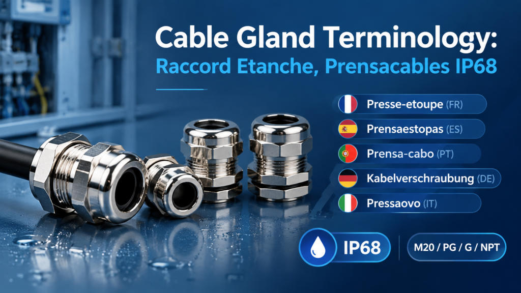
Cable gland terminology in French, Spanish, Portuguese, German and Italian — which words translate, which thread and IP codes never do, and a bilingual RFQ block.
Read More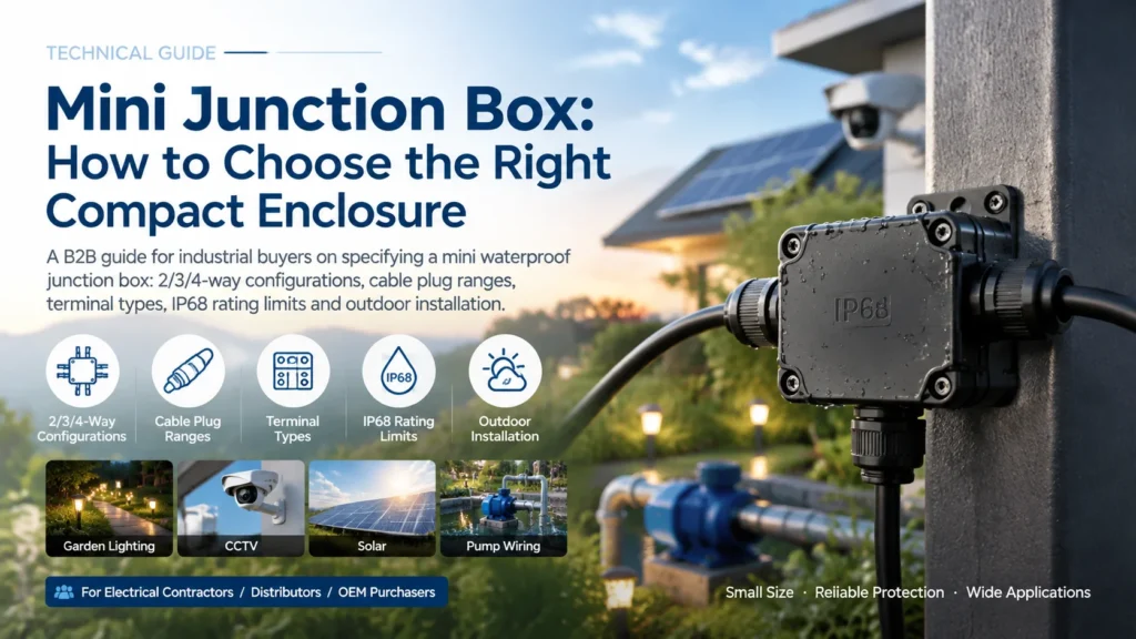
Specify a mini junction box correctly: 2/3/4-way choice, cable plug ranges, terminal types, IP68 limits for burial, and five installation steps that keep the seal.
Read More
When to use a cable gland adaptor, reducer or enlarger: the difference between them, common thread combinations, and how to keep the IP rating when threads do not match.
Read More