Blog
A Quick Guide Buying Flexible Spiral Cable Glands
Buying flexible spiral cable glands: what they are, where they are used, the six points to confirm, how to size them, and nylon vs brass selection.
Read More
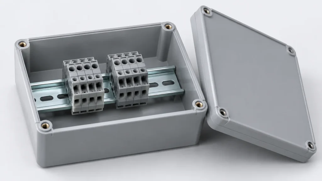
A DIN rail junction box is usually bought for one reason: something inside it has to be removable. Terminal blocks, a small relay, a surge protector or a control board are all easier to service when they unclip rather than unscrew. The problem is that the enclosure has to be deep enough, wide enough and cool enough for the rail and everything on it, and most failures in this category are dimensional rather than electrical. This guide covers the geometry, the mounting options inside the DIN rail junction box you are specifying, and the thermal limit that catches people after installation.
The first thing to settle is which one you are actually buying.
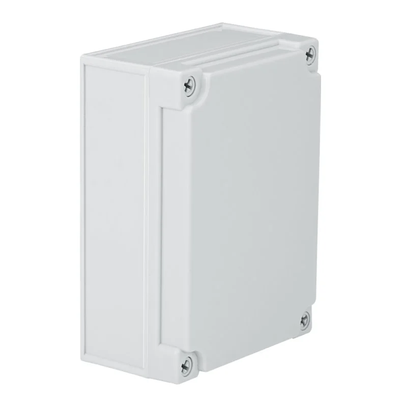
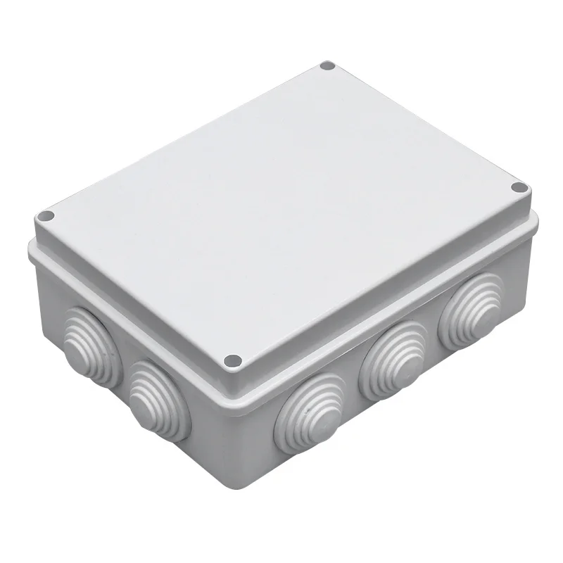
A moulded enclosure with internal mounting points. A plastic box with bosses or threaded inserts in the base, to which you fit a short DIN rail section or a mounting plate. Cable entries are cut to your specification. The JX-RA series belongs here: ABS body, PVC stoppers, IP55 on the smallest size and IP65 across the rest, with inside mounting holes for a PCB or DIN rail and screw or nail fixing outside for walls and boards.
A modular distribution board. A rail with a busbar behind it, designed from the start to hold breakers, usually with a door.
A DIN-rail device housing. A box that clips onto a rail and contains one device. There is no rail inside it.
Only the first type is a junction box in the ordinary sense. A purchase order that says “DIN rail junction box” gets whichever of the three the supplier stocks, so write “enclosure with internal mounting for a 35 mm DIN rail section” if that is what you mean.
DIN rail for small enclosures is the 35 mm top-hat profile in EN 60715, and there are two common heights. The shallow 35 × 7.5 mm rail has a 1 mm wall; the deep 35 × 15 mm rail has a 2.3 mm wall and holds heavier devices more rigidly. Both consume internal depth before anything is mounted; the deep version consumes twice as much.
| Item | Dimension to plan for | Why it matters |
|---|---|---|
| Rail profile | 35 mm wide, 7.5 or 15 mm high | Comes straight off internal depth |
| Module width | 17.5 mm per single pole | Sets how many devices fit across |
| End clearance | About 5 mm each side | Room for end stops and wire bend |
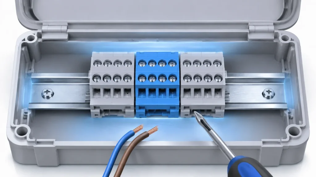
| Wiring space | 25–30 mm in front of terminals | Screwdriver access and cable bend |
Usable rail length is internal width minus end clearance. On a 150 mm wide box with roughly 140 mm inside, that is about 130 mm of rail: seven single-pole modules, or fewer once you allow for end stops and a gap between groups.
Datasheets for this class of enclosure publish external dimensions, not internal ones. The JX-RA table gives L × W × H and the IP rating per size; the wall and lid land have to come off. At typical 3–4 mm walls plus the lid recess, a 150 × 110 × 70 mm box is roughly 140 × 100 × 60 mm inside — about 0.84 L gross and 0.6 L usable. Treat every internal figure as an estimate until you have the drawing or have measured a sample.
What fits in that depth is the part that decides the project.
| What you mount | Typical size | Minimum external height |
|---|---|---|
| DIN terminal block | 5.2 × 47 × 50 mm | 70 mm |
| Small relay or timer module | 17.5 × 80 × 60 mm | 80–120 mm |
| Single-pole MCB | 17.5 × 80 × 70 mm | 120 mm or a distribution board |
The last row is the one that costs money. A 70 mm deep plastic box will not take a miniature circuit breaker with the cover closed, because the breaker plus its rail clip is already about 70 mm deep and the lid land needs another few millimetres. If you need breakers, either go to the 120 mm or 180 mm sizes in the range or specify a distribution board. Terminal blocks and small modules fit comfortably at 70 mm.
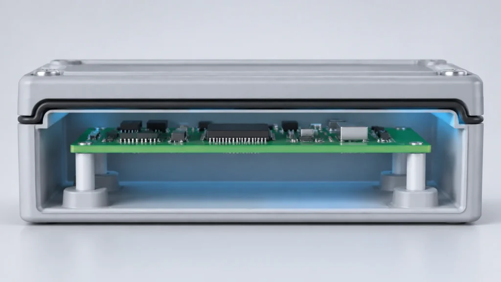
Boards mount on the same bosses. Two details decide whether the assembly survives vibration. The first is boss height: the standoff under the board is what keeps the solder joints off the base and gives convection a path, so specify it rather than accepting whatever the mould provides. The second is board outline against the gasket land — a board that extends to the wall will sit under the lid’s sealing surface, and the lid will then compress the board rather than the gasket.
Leave at least 5 mm between the board edge and the internal wall, keep components below the lid ribs, and confirm the mounting-hole pattern against the moulded bosses before the board is laid out. The JX-RA enclosure data lists the internal mounting provision per size, and a sample is cheaper than a re-spin of the PCB.
A closed enclosure has no fan and no vent, so every watt inside it raises the internal temperature until the walls can reject it. Enclosure manufacturers typically publish about 5–6 W/(m²·K) for unpainted plastic; taking 5.5 for a 150 × 110 × 70 box gives roughly 0.07 m² of surface and about 0.38 W per kelvin, so a 6 W load settles around 16 K above ambient. In a 40 °C plant room that is a 56 °C internal temperature, which is inside the range of industrial electronics but well outside a comfortable margin.
Do the arithmetic before you pick the size. If the number is too high, a larger box helps because surface area grows, but the honest options are a metal enclosure, a lower-loss device, or a shorter service life. Do not add a vent to fix heat: on an IP65 box a vent is a hole. Material choice and its temperature behaviour are covered in our guide to junction box materials.
Start from the device list and work outwards. Four sizes cover most control and communication work in this range, and the IP rating differs across the family — the smallest box is IP55, everything else is IP65.
| Model | L × W × H (mm) | IP | Realistic content |
|---|---|---|---|
| JX-RA85 × 85 × 50 | 85 × 85 × 50 | IP65 | Terminal strip only, no rail |
| JX-RA150 × 110 × 70 | 150 × 110 × 70 | IP65 | ~130 mm rail, terminal blocks |
| JX-RA200 × 155 × 80 | 200 × 155 × 80 | IP65 | Rail plus small relay modules |
| JX-RA255 × 200 × 120 | 255 × 200 × 120 | IP65 | Deeper modules, PCB on standoffs |
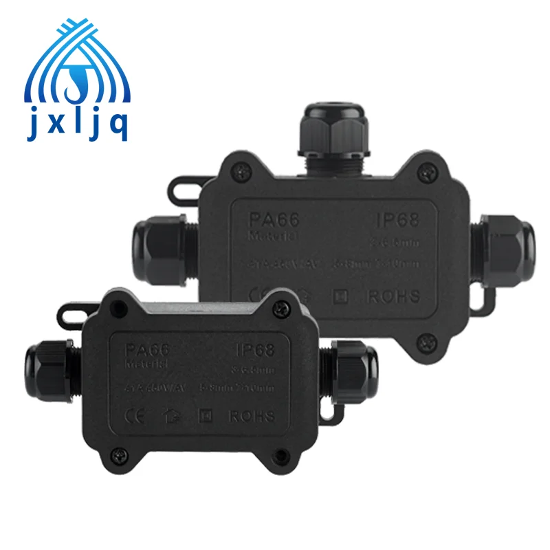
If the application is a compact splice rather than a control point, a moulded mini box with a fixed number of ways is smaller, cheaper and sealed at the factory — the F1 series mini junction box covers that case up to 10 mm cable. Where the internal volume still turns out too small after the arithmetic, the next size up in the JX-AG series goes to 280 × 190 × 180 mm with IP67 and IK08. Sizing by external dimension alone is the most common ordering error here, which is why our junction box size chart works from gross volume downwards.
One more point belongs on the drawing: a fully sealed box that is opened for service collects condensation on the first cold night. If the box is serviced periodically or sits in a humid plant, read our notes on condensation in junction boxes before closing it up.
A DIN rail inside a waterproof box is a packaging problem with three variables: rail height, device depth and surface area for heat. Solve them in that order and the enclosure choice becomes obvious. Solve them afterwards and you will be buying the next size up, or drilling a box that was never rated for the hole.
Only if the base has moulded bosses to fix it to, and only if the internal depth clears the rail plus the device plus wiring space. A 50 mm deep box cannot take a rail and a usable device, and boxes without internal mounting points cannot take one.
Both are 35 mm wide top-hat profiles. The 7.5 mm version has a 1 mm wall and suits terminal blocks and light modules; the 15 mm version has a 2.3 mm wall, sits devices more rigidly and uses twice the depth inside the box.
No. Internal fixings do not touch the sealing surfaces. What does affect the rating is any new hole through the wall, or a board that fouls the lid gasket land so the lid cannot compress it.
None, in practice. The width would take seven single-pole modules, but a breaker with its rail clip is about 70 mm deep and the box has roughly 60 mm inside. Use a distribution board or move up to a 120 mm deep enclosure.

Buying flexible spiral cable glands: what they are, where they are used, the six points to confirm, how to size them, and nylon vs brass selection.
Read More
A marine cable gland is a sealing device used for cable entry in industrial electrical installations, shaped like a sleeve. When a cable passes through the gland, epoxy glue or a compression seal is used to achieve explosion-proof, waterproof, and dust-proof sealing at the enclosure entry point. On a ship, every cable that passes through […]
Read More
Introduction: Why Material Selection Matters in Cable Glands Choosing between a brass cable gland and a stainless steel cable gland is not just a cost decision. It directly affects long-term sealing reliability, corrosion resistance, and system safety in industrial electrical installations. In real-world projects, many failures do not come from the cable gland design itself, […]
Read More