A cable gland case study is only useful if it tells you three things: what failed, why the failure was predictable, and which line of the specification should have read differently. Most published examples skip the first two and jump straight to the outcome, which leaves the reader with a story and nothing transferable. This guide works the other way round. It presents six cable gland case studies from industrial, marine, energy and process installations, each rebuilt around a documented failure mechanism, and traces every failure back to a specification input that was missing, wrong, or simply assumed.
The cases are composites. Identifying details such as site names, contractors, dates and order values have been removed, and the technical content is grounded in published standards and materials behaviour rather than in commercial results. That is deliberate. A project story you cannot audit is marketing; a project story that names the mechanism, the measurement and the corrected specification is engineering, and only the second one is worth your time.
By the end you will have a failure-mode matrix you can carry into a commissioning walk-down, a five-input specification worksheet, and a short list of documents that turn a supplier’s project reference into evidence. If you are scoping a cable gland project of your own, the category overview is a useful companion.
What Makes a Cable Gland Case Study Worth Reading
Search results for a cable gland case study return a predictable mix: application notes dressed up as projects, and vendor pages that quote impressive outcomes without naming a unit, a standard or a measurement. The difference between the two is not length. It is whether the write-up survives four questions.
The Four Parts Every Credible Case Has
A usable case has four parts, and they appear in order.
Situation. The installation conditions, stated in measurable terms: environment, ambient temperature range, chemical or salt exposure, cable type and measured outer diameter, thread standard on the enclosure entry, and the required IP rating.
Failure or challenge. What happened, described physically. “Water inside the enclosure” is a symptom. “Condensation formed because the enclosure was sealed and cycled through a large day-to-night temperature swing” is a mechanism.
Root cause. The single specification input that was wrong, missing or assumed.
Correction and verification. The replacement specification, plus the test that confirmed it: an IP test to IEC 60529, an insulation resistance reading, a continuity reading, or a defined visual inspection interval.
Cases that omit part three are anecdotes. Cases that omit part four are advertisements. Both are common, and both cost buyers money, because a case without a mechanism cannot be compared against your own conditions.
Five Tests for a Project Claim You Cannot Verify
When a supplier hands you a project reference, run these five tests before it goes anywhere near your evaluation matrix.
Physical plausibility. Is the claimed mechanism possible in the stated environment? A claim that a brass entry “never corroded” in continuous salt spray, with no alloy or coating stated, is a warning sign rather than a benefit.
Units and conditions. “Extended service life by two to three times” means nothing without a baseline, an exposure condition and a duration.
Reproducibility. Could your own maintenance team repeat the corrective action from the description alone? If not, the case has no instructional value.
Traceable outcome. Does the result follow from a measurable input — a changed material grade, a corrected thread standard, a recorded torque value — rather than from an unstated cause?
Standard reference. Does the case name the standard the result was tested to? IP performance should reference IEC 60529, general cable gland performance should reference IEC 62444, and hazardous-area installations should reference the IEC 60079 series.
Claim you cannot use
What it is missing
Auditable version
“Reduced downtime by 60%”
Baseline, period, measurement method
“Unplanned entry-related stops fell from four to one per year over two years, counted from maintenance records”
“Glands lasted three times longer”
Exposure condition, inspection interval
“Under annual inspection, the first surface cracking appeared in year five instead of year two”
“Fully waterproof, no failures”
IP rating, test standard, test conditions
“Entries tested to IEC 60529 IP68 at the declared depth and duration after the change”
“Switched to stainless steel and solved it”
Grade, mating materials, coating
“SS316L throughout, including the locknut, removing the brass-to-stainless couple”
“Certified for hazardous areas”
Certificate scope, marking, conditions of use
“Marked for the zone and gas group in scope, with the conditions of use read off the certificate”
Case Study 1 — IP68 on the Bench, Corrosion Offshore
Situation. A coastal installation specified nickel-plated brass glands with stainless steel locknuts, because both parts were individually rated IP68 and both were in stock. The enclosure sat on a jetty structure roughly 50 m from open water, exposed to salt-laden spray and a daily temperature swing.
What happened. At the first inspection cycle, white and green corrosion product appeared around the locknut threads. Three entries then failed a follow-up IP test.
Root cause. Not a sealing failure — a galvanic one. Brass and stainless steel are dissimilar metals, and in a chloride-rich electrolyte film the couple drives corrosion of the less noble material, with the small anode area of the thread concentrating the attack. The IP68 rating described the gland in isolation under test conditions, not the assembled joint in a marine atmosphere.
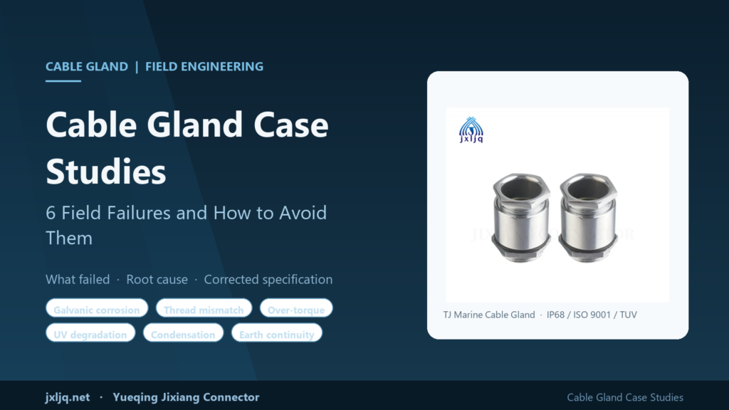
Correction. A single-material-family specification for the exposed path. For instrument and control entries, a chrome-plated brass marine cable gland with an NBR clamping ring, rated IP68 and certified to ISO 9001 and TUV, with an operating range of -40 °C to +110 °C and a 120 °C static maximum, removes the stainless-to-brass couple at the entry itself. Where the exposure demands more corrosion resistance than a plated finish can hold, stainless steel 304 or 316 throughout — including the locknut — keeps the couple homogeneous and eliminates the driving potential difference.
Lesson. Match material families across the whole cable entry, not just the gland body. Where dissimilar metals are unavoidable, break the couple with an isolating washer and state the coating.
Case Study 2 — A Metric Gland in an NPT Knockout
Situation. A skid-mounted control panel arrived with half-inch NPT threaded entries. The installer had M20 glands in stock, and they “nearly fit”. Two turns by hand, then a wrench.
What happened. The metric thread cut into the tapered pipe thread. Engagement looked complete from the outside. On pressure test the joint wept. In a hazardous-area version of the same mistake the consequence is worse than a leak: on an Ex d enclosure the entry thread forms part of the flame path, and forcing a mismatched thread destroys the minimum engagement the design depends on.
Root cause. Thread standards are not interchangeable. M20 × 1.5 is a parallel metric thread to ISO 965. PG threads follow DIN 40430. NPT is a tapered pipe thread to ANSI/ASME B1.20.1 with a 1:16 taper. Mixing them produces a joint that appears to hold but has neither the correct flank contact nor the correct sealing geometry, and no torque value will correct it.
Correction. Never force a thread. Measure the enclosure entry and convert with the right component: a reducer changes a larger thread to a smaller one, an enlarger does the opposite. A reducer in nickel-plated brass, SS304 or SS316L, rated -40 °C to +100 °C with a 120 °C temporary maximum and supplied with a locknut and sealing washer, restores a correct, watertight joint and keeps the entry in the standard it was designed for. On hazardous-area work, the adapter rule also applies: one adapter per entry, and never a blanking plug on top of an adapter.
Lesson. Write the thread standard into the bill of materials, not just the thread size. “M20” and “half-inch NPT” are different parts with different sealing geometry.
Case Study 3 — The Leak Caused by Tightening Too Hard
Situation. Maintenance was asked to stop a weep at a gland entry. The instruction was to make it tighter.
What happened. The dome nut cracked on two entries. On a third, the seal was compressed until it extruded and lost its shape, and the weep got worse. Inspection found stretched threads on the gland body.
Root cause. A cable gland seals at two points, and both are compression joints with a defined working range: between the seal insert and the cable jacket, and between the gland body and the enclosure face. Past the correct compression, the elastomer deforms permanently instead of recovering, and the mechanical parts — usually the weakest thread or the thinnest wall — take the load. Over-torque does not add sealing margin; it removes it, and it removes it silently, because the damage is inside the assembly.
Correction. Replace the damaged parts, re-terminate, and tighten to the manufacturer’s published torque for that size and thread, using a torque wrench or calibrated driver rather than a pipe wrench. Where the cable is smaller than the seal range, fit the correct insert or a reducing seal instead of compressing an oversized insert around a thin cable. If a joint still weeps at the correct torque, the fault is upstream: wrong insert size, a damaged cable jacket, or a scored enclosure face. The full tightening sequence and sealing-point logic is set out in the cable gland torque and sealing points guide.
Lesson. Torque is a specification value, not a judgement call. Record it on the commissioning sheet so the next technician does not have to guess.
Case Study 4 — Nylon Glands That Went Brittle in Direct Sun
Situation. A rooftop array used plastic glands because they were IP68, cost-effective and would not corrode. They were mounted on the outward face of the mounting rail, with an unobstructed southern aspect.
What happened. After several years of exposure, the dome nuts had become brittle. Two cracked when a technician tightened them during a routine check. The enclosures below stayed dry, but the entries had lost their mechanical margin, and a cracked nut is one thermal cycle away from a failed seal.
Root cause. Polyamide absorbs ultraviolet energy, and unstabilised grades lose impact strength and elongation at the surface over years of direct exposure. The IP68 rating was never in question. The failure was mechanical, driven by an environmental input that never made it into the specification: continuous direct solar exposure.
Correction. Treat UV exposure as a material selection input, not an afterthought. Where direct, long-term sunlight is unavoidable, specify a UV-stabilised grade or move the entry to a metal gland in nickel-plated brass or stainless steel. Where plastic is retained for cost or weight, relocate the entry out of direct sun, add a shroud, and shorten the inspection interval so the first sign of surface chalking or cracking triggers replacement. The trade-offs between polymer and metal entries are compared in the nylon versus metal material selection guide.
Lesson. A rating describes one property. A material has to satisfy every property the environment demands, and sunlight is an environment.
Case Study 5 — A Sealed Enclosure That Filled With Water Without Leaking
Situation. An outdoor control cabinet was fitted with IP68 glands and closed with a gasket. It passed a hose test at installation. Six months later there was standing water inside, and every gland was intact.
What happened. The water had not entered through a cable entry. It had condensed. The cabinet heated during the day and cooled at night, the trapped air expanded and contracted, and moist air was drawn in during the cool low-pressure phase, where its water content condensed on cold inner surfaces. The same mechanism, with a larger differential, occurs when a warm sealed enclosure is hosed down with cold water. Enclosures opened during commissioning in humid air start with a moisture load already inside.
Root cause. Sealing and breathing were treated as opposites. A fully sealed enclosure cannot equalise pressure, so every thermal cycle pumps moisture-laden air across the gasket and past the seal lips. Adding more seal does not stop it, because the driving force is pressure, not water.
Correction. Pressure equalisation instead of tighter sealing. A breathable vent plug lets air move while blocking liquid water: waterproof to 3-5 m, with an O-ring rated IP68, an airflow of 325 ml/min at 0.07 bar, resistance to water entry above 5 bar, and an operating range of -40 °C to +120 °C with a 150 °C short-term limit. It is available in stainless steel, nylon PA6, nickel-plated brass and aluminium, and tested for vibration and shock to IEC 60077. Fit it at the highest point of the enclosure, away from direct hose paths, and keep one drainable low point.
Lesson. “Waterproof” and “watertight forever” are different claims. Where temperature cycles exist, specify pressure equalisation from the start rather than as a retrofit.
Case Study 6 — Armoured Cable With No Earth Continuity
Situation. An installation used armoured cable with metal glands. The panel was painted, and the glands were mounted directly onto the painted surface, relying on the armour to provide the earth path.
What happened. Continuity testing found the earth path intermittent, and the reading changed when the gland was moved. The armour was held mechanically, but bonded only through paint and thread contact.
Root cause. Armour and screens are not earth conductors by accident. They need a deliberate, low-impedance bond to the enclosure, and paint, anodising, powder coating and corrosion product are insulators. A second, less obvious fault sits behind it: where a screen is bonded through a short pigtail rather than around its full circumference, the connection behaves as an inductor and its impedance rises with frequency, so it stops working as a shield exactly where shielding matters most.
Correction. Bond deliberately. An earth tag with a PVC shroud provides a defined earthing point on the gland, available for Metric M20 to M100 as well as G and NPT threads, and keeps the connection visible and protected so it survives inspection. On the enclosure side, remove paint at the contact face or fit a dedicated bonding point. For screened and armoured cable in EMC-sensitive installations, specify a gland that terminates the screen through a full 360° contact ring rather than a pigtail.
Lesson. Continuity is a measured value, not an assumption. Put a continuity check and a recorded reading in the commissioning sheet.
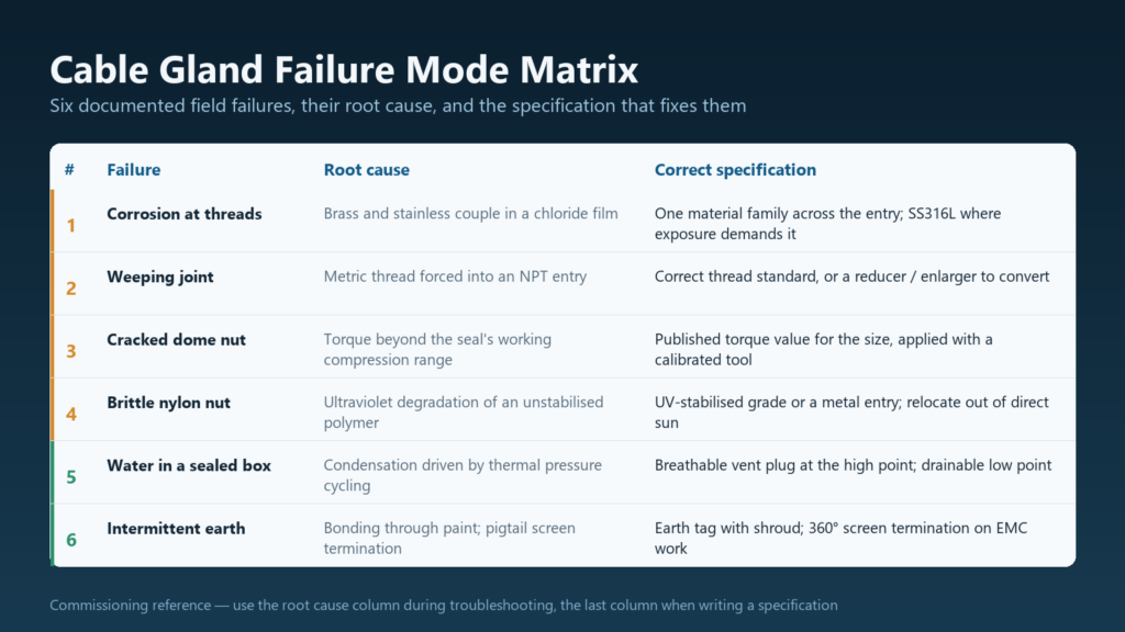
The table below compresses all six cable gland case studies into a single reference. Use the symptom column during troubleshooting and the final column when writing or reviewing a specification.
Case
Symptom
Root cause
Correct specification
1
Corrosion product at threads; IP test failure in salt spray
Galvanic couple between brass and stainless steel in a chloride electrolyte
One material family across the entry, or an isolating washer; SS316L where exposure demands it
2
Weeping joint despite tight appearance; damaged flame path on Ex work
Metric thread forced into an NPT entry; mismatched sealing geometry
Correct thread standard and size, or a reducer or enlarger; minimum engagement maintained
3
Cracked dome nut; extruded seal; stretched body threads
Torque beyond the seal’s working compression range
Published torque value for the size and thread, applied with a calibrated tool
4
Brittle, chalked dome nuts on a sun-exposed array
Ultraviolet degradation of an unstabilised polymer surface
UV-stabilised grade or a metal entry; relocate out of direct sun; shorter inspection interval
5
Standing water inside a sealed enclosure with intact glands
Condensation driven by thermal pressure cycling, not by water ingress
Breathable vent plug at the high point; drainable low point; controlled opening procedure
6
Intermittent or unstable earth continuity reading
Bonding through paint and thread contact; pigtail screen termination
Earth tag with shroud, bare contact face, 360° screen termination on EMC work
What the Six Cases Have in Common
None of the six failures was caused by a defective product. Every one was caused by a specification that was incomplete in the same way: one input was missing, and the missing input was the one that decided the outcome in that environment.
Four gaps account for all six cases.
Environment described only as “outdoor”. Salt spray, ultraviolet light, temperature cycling, washdown chemicals and condensation each impose a different requirement, and the word “outdoor” covers all of them without answering any of them.
Thread standard treated as a size. Metric, PG, G and NPT are different systems with different geometry, and only some of them seal on the thread at all.
Protection rating treated as a single number. IP68 says nothing about corrosion resistance, UV stability, mechanical strength, chemical compatibility or temperature range.
Assembly treated as a judgement call. Torque, thread engagement and bonding are measured values with defined limits, not matters of feel.
The Five Inputs Behind Every Correct Specification
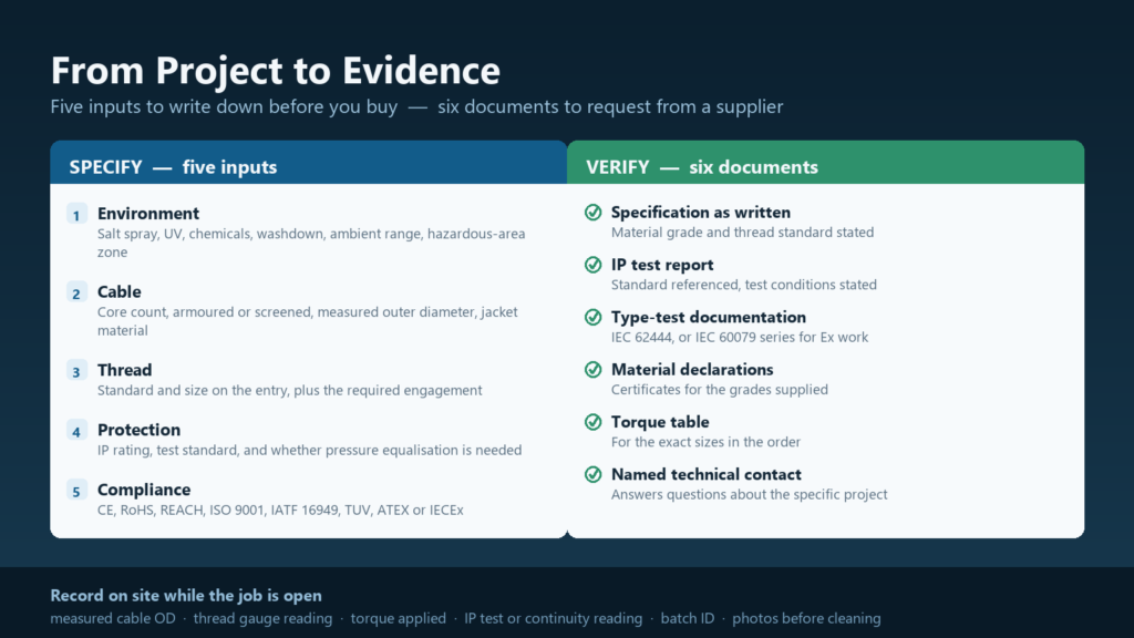
A cable entry specification that will survive a project review answers five questions, and only five.
Input
What to record
How it usually goes wrong
Environment
Salt spray, UV exposure, chemicals, washdown, ambient range, indoor or outdoor, hazardous-area classification
“Outdoor” is written instead of a real exposure profile
Cable
Conductor count, armoured or not, screened or not, measured outer diameter, jacket material
Outer diameter is taken from a datasheet instead of measured on site
Thread
Standard and size on the enclosure entry, plus the required engagement
Size is written without a standard, so the wrong thread arrives
Protection
Required IP rating, test standard, and whether pressure equalisation is needed
The IP rating is copied from a previous project without checking thermal behaviour
Compliance
CE, RoHS, REACH, ISO 9001, IATF 16949, ISO 14001, TUV, and ATEX or IECEx where applicable
Certifications are assumed rather than documented against the certificate scope
A specification built from those five inputs is short, checkable and difficult to argue with. It also makes project references far easier to evaluate, because you can compare a supplier’s case against your own inputs instead of against a story.
How to Turn a Project Into Evidence a Buyer Will Trust
If you are the buyer, the useful question is not “do you have case studies” but “what can you show me from a project like mine”. If you are the supplier or the installer, the same list tells you what to capture while the job is still open, because most of it cannot be reconstructed afterwards. It is also the line that separates a cable gland case study from a testimonial.
What to Record on Site
Photographs of the failure before cleaning, with a scale reference in frame.
The measured cable outer diameter, and the seal range it was matched against.
The thread standard and size of the enclosure entry, checked with a gauge rather than a tape.
The torque value actually applied, and the tool used to apply it.
The ambient temperature range and any chemical or salt exposure the entry sees.
The IP test result or continuity reading taken after the correction.
Batch or lot identification of the replacement parts, for traceability.
What to Ask Your Supplier For
A supplier with genuine project history can produce these six items without inventing them.
The gland specification as written, including material grade and thread standard.
The IP test report, with the standard referenced and the test conditions stated.
Type-test documentation for the gland range: IEC 62444 for general cable glands, the IEC 60079 series for hazardous areas.
Material certificates or declarations for the grades supplied.
The installation torque table for the sizes in the order.
A named technical contact who can answer a question about the specific project.
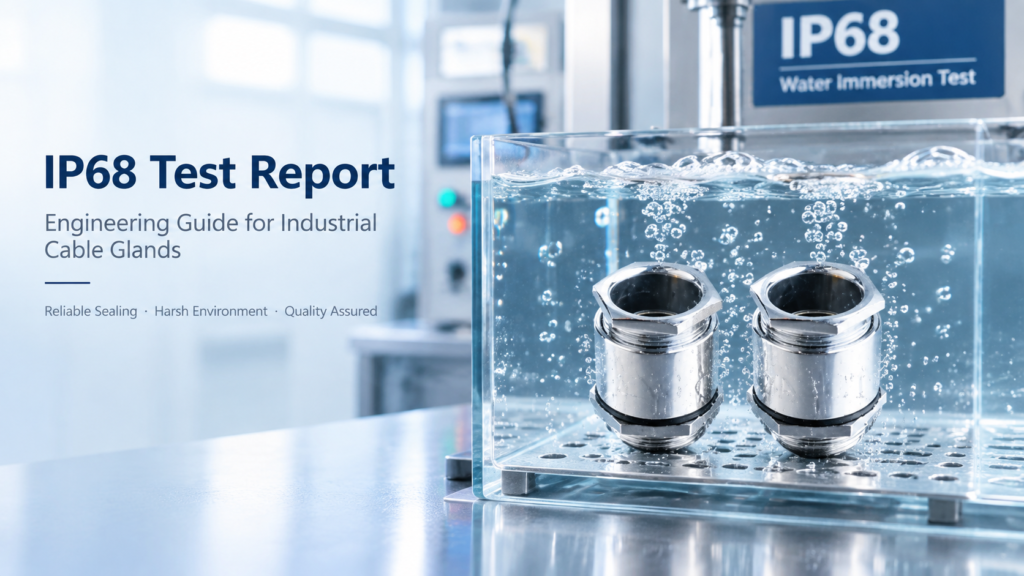
Where an IP claim is central to the project, the report itself is worth reading rather than the badge on the datasheet: what was tested, under what condition, and against which standard. That verification process is set out step by step in the IP68 test report guide for buyers.
Yueqing Jixiang Connector has supplied cable glands, connectors and cable accessories since 2011 from a facility of approximately 5,000 m², operating ISO 9001, IATF 16949 and ISO 14001 management systems with TUV, CE, RoHS, REACH and IP68 documentation. OEM and ODM work covers custom threads, sealing ranges, materials, logos and packaging, two free samples are available for testing and typically ship within 3 to 7 days, and the technical team answers questions about specific installations directly.
Conclusion
Six field failures, one pattern. The gland was rarely the problem; the specification was. Salt spray against a dissimilar-metal couple, a metric thread forced into an NPT entry, a seal compressed past its working range, ultraviolet light on unstabilised polyamide, condensation in a perfectly sealed box, and an earth path that depended on paint. Each of those is a specification input, and each of them is cheap to get right at the drawing stage and expensive to correct after commissioning.
The practical takeaway is short. Write down the environment, the cable, the thread, the protection requirement and the compliance requirement before you choose a part. Then record the torque, the continuity reading and the IP test result after you install it. That is the difference between a project that produces a cable gland case study worth reading and a project that produces a warranty claim.
If you are working through a specific installation and want a second opinion on the specification, send the details through the contact page and the technical team will review them.
Frequently Asked Questions
What is a cable gland case study?
It is a documented record of a real installation that describes the conditions, the failure or challenge, the root cause, and the corrected specification with the test that verified it. A useful one states measurable inputs — cable diameter, thread standard, exposure conditions, IP rating — so a reader can compare them against their own project. Without a root cause and a verification step, it is a product story rather than a case study.
What are the most common cable gland failures in real projects?
Six mechanisms account for most field failures: galvanic corrosion between dissimilar metals in salt or chemical exposure, thread standard mismatch between the gland and the enclosure entry, over-torque that deforms the seal, ultraviolet degradation of polymer parts in direct sun, condensation inside a fully sealed enclosure, and lost earth continuity where armour or screen bonding depends on paint or thread contact. All six are specification problems rather than manufacturing defects.
How do I verify a cable gland project reference?
Ask for the specification as written, the IP test report with its standard and conditions, type-test documentation for the gland range, material declarations, the torque table, and a named technical contact. Then apply the physical plausibility test: the described failure mechanism must be possible in the stated environment, and the outcome must follow from a measurable input rather than an unstated cause.
Why do IP68 cable glands fail in the field?
Usually because the rating was applied to the gland rather than to the assembly. IP68 describes performance under defined test conditions; the installed joint also has to survive the enclosure’s thermal cycling, the thread engagement in the actual entry, the material pair formed with the locknut and enclosure, and the torque that was applied on site. A rating is a starting point for the specification, not a substitute for it.
Should I use brass or stainless steel cable glands for a coastal project?
It depends on the exposure and on what the entry mates with. Nickel-plated or chrome-plated brass is widely used for instrument and control entries in coastal installations where the mating parts are also brass. Where chloride exposure is aggressive or immersion is possible, stainless steel 304 or 316 throughout — including the locknut — avoids the dissimilar-metal couple altogether. The important rule is consistency: do not mix brass bodies with stainless locknuts in a salt-laden atmosphere.
Can a case study replace a type test report?
No. A case study shows how a specification performed in one installation; a type test report shows how a product range performed under defined, repeatable conditions against a named standard. Use the case study to understand the failure mechanisms and the selection logic, and use the type test documentation to confirm that the product you are buying was evaluated to the standard your project requires.
Read IP68 test reports with confidence: what IEC 60529 immersion testing covers for cable glands, what a real report contains, and how to verify a supplier’s IP68 claim before you buy.
What a cable gland factory tour should show you: the 7-stage production chain, injection molding discipline, capacity verification and a 12-point audit checklist.
We use cookies to enhance your browsing experience, serve personalised ads or content, and analyse our traffic. By clicking "Accept All", you consent to our use of cookies.