Blog
Cable Gland Accessories: Lock Nuts, Earth Tags & Sealing Washers
Cable gland accessories explained: locknuts, earth tags, sealing washers, reducers, blanking and vent plugs — and when each one is required.
Read More
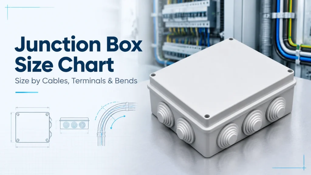
If you searched for a junction box size chart expecting one table to settle the question, you have found two kinds of results instead: North American box-fill tables in cubic inches and AWG, and catalogue pages listing external dimensions with no explanation of what fits inside.
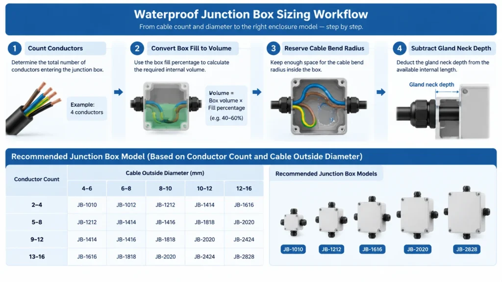
This guide fixes that in the order a purchase happens: the metric size chart our ranges are built against, then the four measurements that decide which row applies — conductor count, conductor size, cable bend radius and the depth your glands steal from the inside wall.
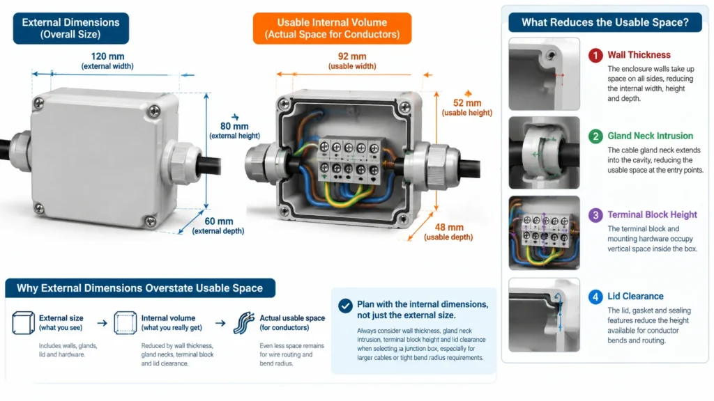
One warning. Sizing a waterproof junction box by external dimensions alone is the most common buying error in incoming RFQs. A box that looks generous on a datasheet can be unusable once a terminal block, a gland neck and a bend radius are inside it.
Our catalogue runs three families, sized differently on purpose: the mini series around cable entries, the AG series around sealed volume, the RA series around moulded entry holes.
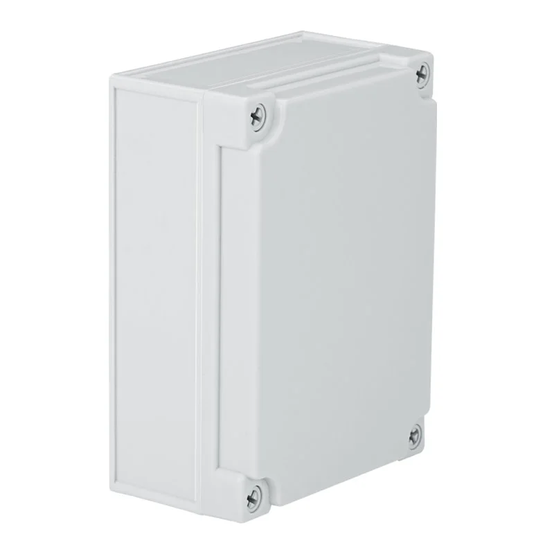
Flat-lid boxes with no moulded knockouts, so entry placement is your design decision rather than a constraint. Gross volume below is external L×W×H only; usable volume is lower.
| Model | External L×W×H (mm) | Gross volume (L) | Weight (kg/pc) | Pcs/ctn |
|---|---|---|---|---|
| JX-090605 | 95×65×55 | 0.34 | 0.12 | 160 |
| JX-110805 | 110×80×50 | 0.44 | 0.14 | 135 |
| JX-110807 | 110×80×70 | 0.62 | 0.16 | 90 |
| JX-110808 | 110×80×85 | 0.75 | 0.19 | 75 |
| JX-101007 | 100×100×75 | 0.75 | 0.18 | 140 |
| JX-101010 | 100×100×100 | 1.00 | 0.21 | 100 |
| JX-130807 | 130×80×70 | 0.73 | 0.19 | 140 |
| JX-121207 | 125×125×75 | 1.17 | 0.25 | 72 |
| JX-180807 | 180×80×70 | 1.01 | 0.24 | 90 |
| JX-250807 | 250×80×70 | 1.40 | 0.28 | 70 |
| JX-171207 | 175×125×75 | 1.64 | 0.32 | 60 |
| JX-171710 | 175×175×100 | 3.06 | 0.49 | 40 |
| JX-201510 | 200×150×100 | 3.00 | 0.43 | 32 |
| JX-202010 | 200×200×100 | 4.00 | 0.59 | 24 |
| JX-251510 | 250×150×100 | 3.75 | 0.55 | 24 |
| JX281913 | 280×190×180 | 9.58 | 0.94 | 12 |
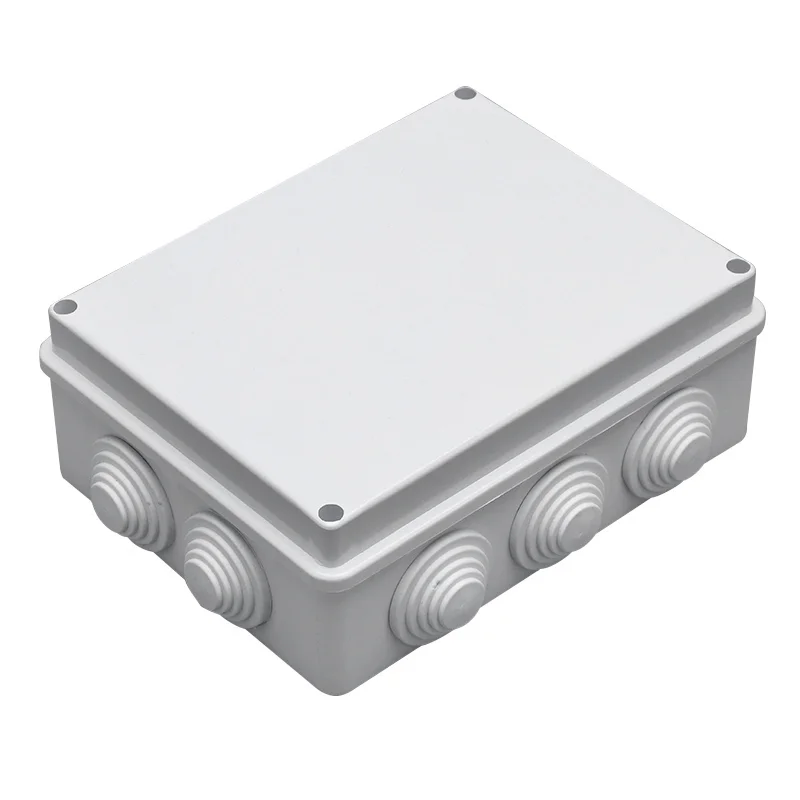
ABS body with PVC stoppers. The decisive column here is not volume but hole quantity: pre-moulded 25 mm or 36 mm entries decide how many cables leave the box with no drilling at all.
| Model | L×W×H (mm) | Entry holes | Hole size (mm) |
|---|---|---|---|
| JX-RA 85×85×50 | 85×85×50 | 7 | 25 |
| JX-RA 100×100×70 | 100×100×70 | 7 | 25 |
| JX-RA 150×110×70 | 150×110×70 | 10 | 25 |
| JX-RA 150×150×70 | 150×150×70 | 8 | 25 |
| JX-RA 200×100×70 | 200×100×70 | 8 | 25 |
| JX-RA 200×155×80 | 200×155×80 | 10 | 36 |
| JX-RA 200×200×80 | 200×200×80 | 12 | 36 |
| JX-RA 255×200×120 | 255×200×120 | 12 | 36 |
| JX-RA 300×250×120 | 300×250×120 | 12 | 36 |
| JX-RA 400×350×120 | 400×350×120 | 16 | 36 |
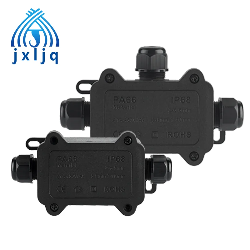
Under roughly 0.3 litres, rectangular boxes stop making sense and moulded splice enclosures take over. The F1 range is IP68, moulded in flame-retardant PA6 nylon with a silicone O-ring, in 2-way, 3-way and 4-way entries for 3–6.5 mm, 5–8 mm and 7–10 mm cable, terminated by screw-crimping onto nickel-plated 59-1 brass contacts rated 16 A/450 V and 24 A/450 V by model, for 0.5–4 mm² and 0.5–2.5 mm² conductors. If the job fits an F1, compare entry counts instead of volume — the F1-2T/3T/4T mini waterproof junction box page carries the ordering table.
Count every current-carrying conductor spliced or terminated inside, including neutrals. All equipment earths count as one allowance, not one each. Internal clamps count as one, and each type of support fitting counts once. Conductors passing straight through without a joint add nothing under most wiring rules.
Metric and North American practice then part company. IEC 60670-22 sets construction, marking and protection requirements for connecting boxes but publishes no box-fill table; the cubic-inch arithmetic buyers see quoted comes from national wiring rules. NEC Article 314.16 is the version most often referenced.
| Conductor size | Allowance per conductor | Metric equivalent |
|---|---|---|
| 14 AWG | 2.00 cu in | ≈32.8 cm³ |
| 12 AWG | 2.25 cu in | ≈36.9 cm³ |
| 10 AWG | 2.50 cu in | ≈41.0 cm³ |
| 8 AWG | 3.00 cu in | ≈49.2 cm³ |
| 6 AWG | 5.00 cu in | ≈81.9 cm³ |
The table stops at 6 AWG; conductors above that fall under the pull-box rules of NEC 314.28, which work from raceway size rather than conductor count. Working in millimetres, convert cubic inches to litres by dividing by 61.02.
Sanity check: a 100×100×75 mm box is 0.75 gross litres, about 45.8 cu in. At 0.60 L of actual internal space, roughly 36.6 cu in, the arithmetic allows sixteen 12 AWG allowances — generous, until sixteen conductors, two glands and a screwdriver share the same cavity.
Conductors must turn inside without being forced. A common field rule of thumb is a minimum bend radius of six times the cable outside diameter for fixed installation, though the figure varies with cable construction and the standard you work to — confirm against the cable datasheet.
That rule reshapes the chart. A 10 mm cable needs roughly 60 mm of free radius, so at least 60 mm of clear internal dimension in the direction it turns. On a JX-AG the rule applies inside: the 95×65×55 model leaves 55 mm of internal height, marginal for a 10 mm cable that must turn. Choose the depth column before the length column. On an F1 the cable is gripped by the seal and turns outside the body, so the rule does not apply.
| Constraint | What it costs | How to check |
|---|---|---|
| Gland neck intrusion | 10–15 mm internal depth per entry | Thread length minus wall thickness |
| Spanner clearance | About one gland diameter of flat wall between entries | Draw the wall to scale before drilling |
| Flat wall area | Caps entry count regardless of volume | Measure flat faces only, not corner radii |
The JX-RA series sidesteps the calculation: holes are moulded at 25 or 36 mm and blanked with PVC stoppers, so capacity is published rather than derived. Seven holes on an 85×85 mm box is generous for lighting circuits and tight on a control panel where every hole carries a gland plus a ferrule. If glands are still open, size them first with the cable gland size chart for metric, PG and NPT threads, then size the box around the result.
Four 4-core 2.5 mm² armoured cables, joined, outdoor wall. Sixteen conductors, earths as one allowance, clamps as one more: eighteen allowances at 2.25 cu in gives 40.5 cu in, about 0.66 L of fill. A 100×100×75 box offers 0.60 L, so it is short. JX-101010 at 1.00 L or JX-121207 at 1.17 L gives real margin, and both take four M20 glands on the long faces without crowding.
Twelve 1.5 mm² control conductors plus a DIN-rail relay, indoor cabinet. Fill volume is modest; the relay needs flat mounting area and depth. JX-RA 200×200×80 offers twelve 36 mm moulded holes and internal mounting points for PCB or DIN rail, while JX-AG 200×200×100 gives more headroom but no moulded entries, so you drill sixteen holes yourself.
For how enclosure class changes the sizing logic altogether, see waterproof junction box vs distribution box. For the selection sequence that sits above this chart, read the IP68 waterproof junction box selection guide.
A junction box size chart is a starting point, not an answer. Read it in this order: conductors first, volume second, bend radius third, entry capacity last. If the arithmetic lands between two rows, take the larger — the cost difference on a moulded enclosure is small, and the cost of a box that cannot be wired is not.
Send us the conductor schedule, cable outside diameters and gland plan and we will return the model and quantity that fits, with the internal dimensions you need for your drawing. Send the schedule to our engineering team and we will confirm sizing against the current datasheet.
Count conductor allowances rather than cables, convert to volume with your wiring rule, compare against internal rather than external volume, then confirm the bend radius and gland necks still fit in what remains.
There is no single standard. Moulded plastic enclosures commonly run from about 85×85×50 mm to 300×250×120 mm, with wall-mounting sizes up to roughly 400×350×120 mm. Small splice enclosures sit below that and are dimensioned by cable range instead.
No. A larger box costs more and needs more wall area. But an undersized box cannot be reworked and dissipates heat poorly. One size above the calculated minimum is the practical compromise.
Indirectly, yes. Higher protection means thicker walls, more sealing geometry and deeper gland necks, all of which reduce usable internal space for the same external dimensions.
No. External dimensions include wall thickness, lid skirt and mounting features. For a moulded plastic box, usable internal volume typically runs 70–80 % of the gross figure, and less again once a terminal block and entries are installed.

Cable gland accessories explained: locknuts, earth tags, sealing washers, reducers, blanking and vent plugs — and when each one is required.
Read More
The official profile of Jixiang Connector (Yueqing Jixiang Connector Co., Ltd.): products, certifications, MOQ, lead times and how to verify the factory before ordering.
Read More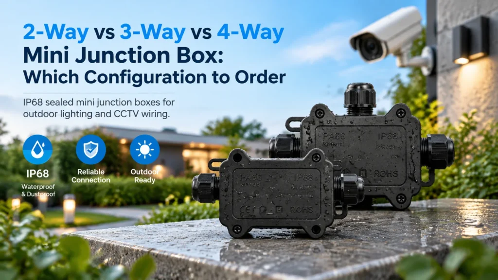
2-way, 3-way or 4-way? How entry count changes the box you order, with the full F1 order-code table, cable ranges and the conductor limit most buyers miss.
Read More